
Service Manual
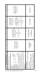


Table Of Contents
- Safety Notices
- Definitions
- General Information
- Installation
- Maintenance
- Operation
- Troubleshooting
- Troubleshooting
- Troubleshooting By Symptom
- Reset To Factory Defaults
- Symptom #1 - Ice Machine Will Not Run
- #2 - Low Production, Long Freeze Cycle
- Symptom #2 - Freeze Cycle Refrigeration System Operational Analysis Tables
- Symptom #3 & #4 - Harvest Problems Self‑contained Air, Water & Remote Condenser Models
- Symptom #3 - Self-Contained Air or Water-cooled
- Symptom #3 - Remote Condenser
- Symptom #4 - Self-Contained Air, Water-Cooled or Remote
- Component Check Procedures
- Electrical Components
- Control Board, Display And Touchscreen
- Control Board Relay Test
- Programming A Replacement Control Board
- USB Flash Drive Specifications and Formatting
- Exporting Data to a Flash Drive
- Upgrading Firmware with a Flash Drive
- Main Fuse
- Bin Switch
- Water Level Control Circuitry
- Ice Thickness Probe (Initiates Harvest)
- Bin Level Probe
- Thermistors
- High Pressure Cutout (HPCO) Control
- Fan Cycle Control
- Harvest Assist Air Pump
- Compressor Electrical Diagnostics
- Diagnosing Start Components
- Refrigeration Components
- Refrigerant Recovery/Evacuation
- System Contamination Clean-Up
- Liquid Line Filter-Driers
- Replacing Pressure Controls Without Removing Refrigerant Charge
- Total System Refrigerant Charge
- Electrical Components
- Charts
- Diagrams
- Wiring Diagrams
- Wiring Diagram Legend
- IF0300/IT0420/IT0450/IT0500/IT0620/IT0750 1ph Air/Water
- IT0500/IT1200 - 1ph Remote Air-Cooled
- IF0600/IF0900/IT0900/IT1200 - 1ph Air/Water
- IF0600/IF0900/IT0900/IT1200 - 3ph Air/Water
- IT1500/IT1900 - 1ph Air/Water
- IT1500/IT1900 - 3 ph Air/Water
- IF0500/IF0600/IF0900/IT1200/IF1500 - 1ph Remote
- IF0500/IF0600/IF0900/IT1200/IF1500 - 3ph Remote Condenser
- Electronic Control Board
- Refrigeration Tubing Schematics
- Wiring Diagrams

Part Number: 000015430 Rev 02 5/20 103
Discharge Line Temperature
Record freeze cycle discharge line
temperature at the end of the
freeze cycle.
T2 _________°F (°C)
Reference “Discharge Line
Temperature Analysis” on page
123
Discharge line temp.
150°F (65°C)
or higher at the end of
the freeze cycle
Discharge line temp.
150°F (65°C)
or higher at the end of
the freeze cycle
Discharge line temp.
less than
150°F (65°C) at the end
of the freeze cycle
Discharge line temp.
150°F (65°C) or higher
at the end of the freeze
cycle
Wait 5 minutes into the freeze
cycle.
Compare temperatures of
compressor discharge line and
harvest valve inlet.
Reference “Harvest Valve
Analysis” on page 121
The harvest valve inlet
is Hot
-and-
approaches the
temperature of a Hot
compressor discharge
line.
The harvest valve inlet
is Cool enough to hold
hand on
-and-
the compressor
discharge line is Hot.
The harvest valve inlet
is Cool enough to hold
hand on
-and-
the compressor
discharge line is Cool
enough to hold hand on.
The harvest valve inlet
is Cool enough to hold
hand on
-and-
the compressor
discharge line is Hot.