
Service Manual

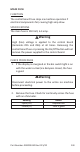


Table Of Contents
- Safety Notices
- Definitions
- General Information
- Installation
- Maintenance
- Operation
- Troubleshooting
- Troubleshooting
- Troubleshooting By Symptom
- Reset To Factory Defaults
- Symptom #1 - Ice Machine Will Not Run
- #2 - Low Production, Long Freeze Cycle
- Symptom #2 - Freeze Cycle Refrigeration System Operational Analysis Tables
- Symptom #3 & #4 - Harvest Problems Self‑contained Air, Water & Remote Condenser Models
- Symptom #3 - Self-Contained Air or Water-cooled
- Symptom #3 - Remote Condenser
- Symptom #4 - Self-Contained Air, Water-Cooled or Remote
- Component Check Procedures
- Electrical Components
- Control Board, Display And Touchscreen
- Control Board Relay Test
- Programming A Replacement Control Board
- USB Flash Drive Specifications and Formatting
- Exporting Data to a Flash Drive
- Upgrading Firmware with a Flash Drive
- Main Fuse
- Bin Switch
- Water Level Control Circuitry
- Ice Thickness Probe (Initiates Harvest)
- Bin Level Probe
- Thermistors
- High Pressure Cutout (HPCO) Control
- Fan Cycle Control
- Harvest Assist Air Pump
- Compressor Electrical Diagnostics
- Diagnosing Start Components
- Refrigeration Components
- Refrigerant Recovery/Evacuation
- System Contamination Clean-Up
- Liquid Line Filter-Driers
- Replacing Pressure Controls Without Removing Refrigerant Charge
- Total System Refrigerant Charge
- Electrical Components
- Charts
- Diagrams
- Wiring Diagrams
- Wiring Diagram Legend
- IF0300/IT0420/IT0450/IT0500/IT0620/IT0750 1ph Air/Water
- IT0500/IT1200 - 1ph Remote Air-Cooled
- IF0600/IF0900/IT0900/IT1200 - 1ph Air/Water
- IF0600/IF0900/IT0900/IT1200 - 3ph Air/Water
- IT1500/IT1900 - 1ph Air/Water
- IT1500/IT1900 - 3 ph Air/Water
- IF0500/IF0600/IF0900/IT1200/IF1500 - 1ph Remote
- IF0500/IF0600/IF0900/IT1200/IF1500 - 3ph Remote Condenser
- Electronic Control Board
- Refrigeration Tubing Schematics
- Wiring Diagrams

148 Part Number: 000015430 Rev 02 5/20
Prechill & Freeze Cycle Operation
The water inlet valve energizes and de-energizes in
conjunction with the water level probe located in the
water trough.
• The water inlet valve is ON when there is no water in
contact with the water level probes.
• The water inlet valve turns OFF after water contacts
the water level probes for 6 continuous seconds.
• The water inlet valve can cycle ON and OFF once in the
prechill and up to two times in the freeze cycle.
• Maximum fill time is:
• Single evaporator 12 minutes.
• Dual evaporator 16 minutes.
The water inlet valve energizes in the Prechill cycle and will
de-energize if water touches the high level probe (in most
instances the water trough can’t fill in the prechill cycle
and the water inlet valve will remain energized into the
freeze cycle). The water inlet valve will remain energized
until water contacts the high water probe. The water inlet
valve will cycle ON, and then OFF one more time to refill
the water trough. The water inlet valve is now OFF for the
duration of the freeze cycle.
REVERSE OSMOSIS OR DEIONIZED WATER USAGE
When using water with low total dissolved solid content
(low TDS) the water level probe sensitivity can be
increased by moving the jumper over one pin (refer to
for location).
The Electronic Control Board diagrams shows the default
position of the jumper covering the left and center pins.
Moving the jumper to the center and right pins and
enabling R.O. menu “Use less water with reverse osmosis”
will increase the sensitivity of the water level probe.
See for menu item location.