
Service Manual
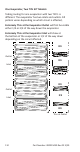
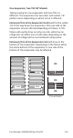

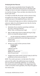


Table Of Contents
- Safety Notices
- Definitions
- General Information
- Installation
- Maintenance
- Operation
- Troubleshooting
- Troubleshooting
- Troubleshooting By Symptom
- Reset To Factory Defaults
- Symptom #1 - Ice Machine Will Not Run
- #2 - Low Production, Long Freeze Cycle
- Symptom #2 - Freeze Cycle Refrigeration System Operational Analysis Tables
- Symptom #3 & #4 - Harvest Problems Self‑contained Air, Water & Remote Condenser Models
- Symptom #3 - Self-Contained Air or Water-cooled
- Symptom #3 - Remote Condenser
- Symptom #4 - Self-Contained Air, Water-Cooled or Remote
- Component Check Procedures
- Electrical Components
- Control Board, Display And Touchscreen
- Control Board Relay Test
- Programming A Replacement Control Board
- USB Flash Drive Specifications and Formatting
- Exporting Data to a Flash Drive
- Upgrading Firmware with a Flash Drive
- Main Fuse
- Bin Switch
- Water Level Control Circuitry
- Ice Thickness Probe (Initiates Harvest)
- Bin Level Probe
- Thermistors
- High Pressure Cutout (HPCO) Control
- Fan Cycle Control
- Harvest Assist Air Pump
- Compressor Electrical Diagnostics
- Diagnosing Start Components
- Refrigeration Components
- Refrigerant Recovery/Evacuation
- System Contamination Clean-Up
- Liquid Line Filter-Driers
- Replacing Pressure Controls Without Removing Refrigerant Charge
- Total System Refrigerant Charge
- Electrical Components
- Charts
- Diagrams
- Wiring Diagrams
- Wiring Diagram Legend
- IF0300/IT0420/IT0450/IT0500/IT0620/IT0750 1ph Air/Water
- IT0500/IT1200 - 1ph Remote Air-Cooled
- IF0600/IF0900/IT0900/IT1200 - 1ph Air/Water
- IF0600/IF0900/IT0900/IT1200 - 3ph Air/Water
- IT1500/IT1900 - 1ph Air/Water
- IT1500/IT1900 - 3 ph Air/Water
- IF0500/IF0600/IF0900/IT1200/IF1500 - 1ph Remote
- IF0500/IF0600/IF0900/IT1200/IF1500 - 3ph Remote Condenser
- Electronic Control Board
- Refrigeration Tubing Schematics
- Wiring Diagrams
120 Part Number: 000015430 Rev 02 5/20
Comparing Evaporator Inlet and Outlet Temperatures -
Valve Machines
The temperatures of the suction lines entering and leaving
the evaporator alone cannot diagnose an ice machine.
However, comparing these temperatures during the
freeze cycle, along with using Manitowoc’s Freeze Cycle
Refrigeration System Operational Analysis Table, can help
diagnose an ice machine malfunction.
The actual temperatures entering and leaving the
evaporator vary by model, and change throughout the
freeze cycle. This makes documenting the “normal”
inlet and outlet temperature readings difficult. The key
to the diagnosis lies in the difference between the two
temperatures five minutes into the freeze cycle. These
temperatures should be within 7° of each other.
Use this procedure to document freeze cycle inlet and
outlet temperatures.
1. Navigate to Service/Diagnostics/Temperature Sensors.
2. Wait 5 minutes into the freeze cycle.
3. Record the evaporator inlet (T3) and outlet (T4)
temperatures at 5 minutes into the freeze cycle.
Determine the difference.
4. Record the information on the table.