
Service Manual
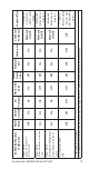


Table Of Contents
- Safety Notices
- Definitions
- General Information
- Installation
- Maintenance
- Operation
- Troubleshooting
- Troubleshooting
- Troubleshooting By Symptom
- Reset To Factory Defaults
- Symptom #1 - Ice Machine Will Not Run
- #2 - Low Production, Long Freeze Cycle
- Symptom #2 - Freeze Cycle Refrigeration System Operational Analysis Tables
- Symptom #3 & #4 - Harvest Problems Self‑contained Air, Water & Remote Condenser Models
- Symptom #3 - Self-Contained Air or Water-cooled
- Symptom #3 - Remote Condenser
- Symptom #4 - Self-Contained Air, Water-Cooled or Remote
- Component Check Procedures
- Electrical Components
- Control Board, Display And Touchscreen
- Control Board Relay Test
- Programming A Replacement Control Board
- USB Flash Drive Specifications and Formatting
- Exporting Data to a Flash Drive
- Upgrading Firmware with a Flash Drive
- Main Fuse
- Bin Switch
- Water Level Control Circuitry
- Ice Thickness Probe (Initiates Harvest)
- Bin Level Probe
- Thermistors
- High Pressure Cutout (HPCO) Control
- Fan Cycle Control
- Harvest Assist Air Pump
- Compressor Electrical Diagnostics
- Diagnosing Start Components
- Refrigeration Components
- Refrigerant Recovery/Evacuation
- System Contamination Clean-Up
- Liquid Line Filter-Driers
- Replacing Pressure Controls Without Removing Refrigerant Charge
- Total System Refrigerant Charge
- Electrical Components
- Charts
- Diagrams
- Wiring Diagrams
- Wiring Diagram Legend
- IF0300/IT0420/IT0450/IT0500/IT0620/IT0750 1ph Air/Water
- IT0500/IT1200 - 1ph Remote Air-Cooled
- IF0600/IF0900/IT0900/IT1200 - 1ph Air/Water
- IF0600/IF0900/IT0900/IT1200 - 3ph Air/Water
- IT1500/IT1900 - 1ph Air/Water
- IT1500/IT1900 - 3 ph Air/Water
- IF0500/IF0600/IF0900/IT1200/IF1500 - 1ph Remote
- IF0500/IF0600/IF0900/IT1200/IF1500 - 3ph Remote Condenser
- Electronic Control Board
- Refrigeration Tubing Schematics
- Wiring Diagrams
74 Part Number: 000015430 Rev 02 5/20
Ice Thickness Probe
The freeze cycle continues until the six minute freeze lock
expires and enough ice has formed to send a signal from
the ice thickness probe to the control board.
During the first 6 minutes of the freeze cycle the ice
thickness probe microphone samples ambient noise.
6 minutes into the freeze cycle 4 baseline readings are
recorded. Ice formation on the evaporator will change
the readings; when two of the four baseline readings are
exceeded a harvest cycle starts.
Harvest Sequence
5. Water Purge
The air pump (when used) the harvest valve(s) and
harvest pressure regulating valve (HPR) energize to divert
refrigerant gas to the evaporator.
The water pump continues to run, and the water dump
valve energizes to purge the water in the water trough.
6. Harvest
The harvest valve, air pump(s) and harvest pressure
regulating (HPR) solenoid valves remain energized and the
refrigerant gas warms the evaporator causing the cubes to
slide, as a sheet, off the evaporator and into the storage
bin. If the damper/curtain does not open within 3.5
minutes in the harvest cycle the following occurs:
• 3.5 minutes - The water inlet valve energizes until
water touches the high water level probe.
• 4 minutes - The water pump energizes.
• 6.5 to 7 minutes - The water dump valve energizes.
When the sliding sheet of cubes opens and closes within
30 seconds the bin switch terminates the harvest sequence
and returns the ice machine to the freeze sequence (step
3 - 4).
NOTE: If bin switch does not open before 7 minutes the ice
machine will start a Thaw Cycle - Refer to “Thaw Cycle” on
page 86 for details.