
Service Manual
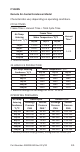


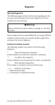

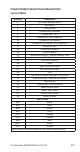


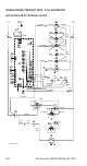
Table Of Contents
- Safety Notices
- Definitions
- General Information
- Installation
- Maintenance
- Operation
- Troubleshooting
- Troubleshooting
- Troubleshooting By Symptom
- Reset To Factory Defaults
- Symptom #1 - Ice Machine Will Not Run
- #2 - Low Production, Long Freeze Cycle
- Symptom #2 - Freeze Cycle Refrigeration System Operational Analysis Tables
- Symptom #3 & #4 - Harvest Problems Self‑contained Air, Water & Remote Condenser Models
- Symptom #3 - Self-Contained Air or Water-cooled
- Symptom #3 - Remote Condenser
- Symptom #4 - Self-Contained Air, Water-Cooled or Remote
- Component Check Procedures
- Electrical Components
- Control Board, Display And Touchscreen
- Control Board Relay Test
- Programming A Replacement Control Board
- USB Flash Drive Specifications and Formatting
- Exporting Data to a Flash Drive
- Upgrading Firmware with a Flash Drive
- Main Fuse
- Bin Switch
- Water Level Control Circuitry
- Ice Thickness Probe (Initiates Harvest)
- Bin Level Probe
- Thermistors
- High Pressure Cutout (HPCO) Control
- Fan Cycle Control
- Harvest Assist Air Pump
- Compressor Electrical Diagnostics
- Diagnosing Start Components
- Refrigeration Components
- Refrigerant Recovery/Evacuation
- System Contamination Clean-Up
- Liquid Line Filter-Driers
- Replacing Pressure Controls Without Removing Refrigerant Charge
- Total System Refrigerant Charge
- Electrical Components
- Charts
- Diagrams
- Wiring Diagrams
- Wiring Diagram Legend
- IF0300/IT0420/IT0450/IT0500/IT0620/IT0750 1ph Air/Water
- IT0500/IT1200 - 1ph Remote Air-Cooled
- IF0600/IF0900/IT0900/IT1200 - 1ph Air/Water
- IF0600/IF0900/IT0900/IT1200 - 3ph Air/Water
- IT1500/IT1900 - 1ph Air/Water
- IT1500/IT1900 - 3 ph Air/Water
- IF0500/IF0600/IF0900/IT1200/IF1500 - 1ph Remote
- IF0500/IF0600/IF0900/IT1200/IF1500 - 3ph Remote Condenser
- Electronic Control Board
- Refrigeration Tubing Schematics
- Wiring Diagrams

Part Number: 000015430 Rev 02 5/20 235
Wiring Diagrams
The following pages contain electrical wiring diagrams. Be
sure you are referring to the correct diagram for the ice
machine you are servicing.
n
Warning
Always disconnect power before working on electrical
circuitry.
Some components are wired differently on energy efficient
machines. Please verify your model number (page 19) to
reference the correct diagrams.
WIRING DIAGRAM LEGEND
The following symbols are used on all of the wiring
diagrams:
* Internal Compressor Overload
(Some models have external compressor overloads)
** Fan Motor Run Capacitor
(Some models do not incorporate fan motor run capacitor)
( ) Wire Number Designation
(The number is marked at each end of the wire)
—>>— Multi-Pin Connection
—> (Electrical Box Side)
>— (Compressor Compartment Side)
Diagrams