
Service Manual
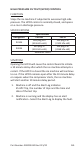

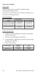
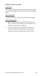

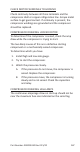
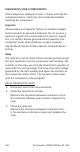
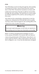

Table Of Contents
- Safety Notices
- Definitions
- General Information
- Installation
- Maintenance
- Operation
- Troubleshooting
- Troubleshooting
- Troubleshooting By Symptom
- Reset To Factory Defaults
- Symptom #1 - Ice Machine Will Not Run
- #2 - Low Production, Long Freeze Cycle
- Symptom #2 - Freeze Cycle Refrigeration System Operational Analysis Tables
- Symptom #3 & #4 - Harvest Problems Self‑contained Air, Water & Remote Condenser Models
- Symptom #3 - Self-Contained Air or Water-cooled
- Symptom #3 - Remote Condenser
- Symptom #4 - Self-Contained Air, Water-Cooled or Remote
- Component Check Procedures
- Electrical Components
- Control Board, Display And Touchscreen
- Control Board Relay Test
- Programming A Replacement Control Board
- USB Flash Drive Specifications and Formatting
- Exporting Data to a Flash Drive
- Upgrading Firmware with a Flash Drive
- Main Fuse
- Bin Switch
- Water Level Control Circuitry
- Ice Thickness Probe (Initiates Harvest)
- Bin Level Probe
- Thermistors
- High Pressure Cutout (HPCO) Control
- Fan Cycle Control
- Harvest Assist Air Pump
- Compressor Electrical Diagnostics
- Diagnosing Start Components
- Refrigeration Components
- Refrigerant Recovery/Evacuation
- System Contamination Clean-Up
- Liquid Line Filter-Driers
- Replacing Pressure Controls Without Removing Refrigerant Charge
- Total System Refrigerant Charge
- Electrical Components
- Charts
- Diagrams
- Wiring Diagrams
- Wiring Diagram Legend
- IF0300/IT0420/IT0450/IT0500/IT0620/IT0750 1ph Air/Water
- IT0500/IT1200 - 1ph Remote Air-Cooled
- IF0600/IF0900/IT0900/IT1200 - 1ph Air/Water
- IF0600/IF0900/IT0900/IT1200 - 3ph Air/Water
- IT1500/IT1900 - 1ph Air/Water
- IT1500/IT1900 - 3 ph Air/Water
- IF0500/IF0600/IF0900/IT1200/IF1500 - 1ph Remote
- IF0500/IF0600/IF0900/IT1200/IF1500 - 3ph Remote Condenser
- Electronic Control Board
- Refrigeration Tubing Schematics
- Wiring Diagrams

168 Part Number: 000015430 Rev 02 5/20
DIAGNOSING START COMPONENTS
If the compressor attempts to start, or hums and trips the
overload protector, check the start components before
replacing the compressor.
Capacitor
Visual evidence of capacitor failure can include a bulged
terminal end or a ruptured membrane. Do not assume a
capacitor is good if no visual evidence is present. A good
test is to install a known good substitute capacitor. Use
a capacitor tester when checking a suspect capacitor.
Clip the bleed resistor off the capacitor terminals before
testing.
Relay
The relay has a set of contacts that connect and disconnect
the start capacitor from the compressor start winding. The
contacts on the relay are normally closed (start capacitor in
series with the start winding). The relay senses the voltage
generated by the start winding and opens the contacts as
the compressor motor starts. The contacts remain open
until the compressor is de-energized.
RELAY OPERATION CHECK
1. Disconnect wires from relay terminals.
2. Verify the contacts are closed.
Measure the resistance between terminals 1 and 2.
No continuity indicates open contacts. Replace the
relay.
3. Check the relay coil.
Measure the resistance between terminals 2 and
5. No resistance indicates an open coil. Replace the
relay.