Indigo NXT Ice Machines Installation, Operation and Maintenance Manual , Caution Original Document Read this instruction before operating this equipment.
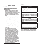
Safety Notices Safety Notices Read these precautions to prevent personal injury: • Read this manual thoroughly before operating, installing or performing maintenance on the equipment. Failure to follow instructions in this manual can cause property damage, injury or death. • Routine adjustments and maintenance procedures outlined in this manual are not covered by the warranty. • Proper installation, care and maintenance are essential for maximum performance and troublefree operation of your equipment.
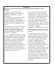
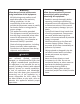
nWarning Follow these precautions to prevent personal injury during installation of this equipment: • Installation must comply with all • Legs or casters must be installed and applicable equipment fire and health the legs/casters must be screwed in codes with the authority having completely. When casters are installed jurisdiction. the mass of this unit will allow it to move uncontrolled on an inclined surface.
nWarning Follow these electrical requirements during installation of this equipment. • All field wiring must conform to all applicable codes of the authority having jurisdiction. It is the responsibility of the end user to provide the disconnect means to satisfy local codes. Refer to rating plate for proper voltage. • This appliance must be grounded. • This equipment must be positioned so that the plug is accessible unless other means for disconnection from the power supply (e.g.
DANGER Follow these precautions to prevent personal injury during use and maintenance of this equipment: • It is the responsibility of the equipment • Units with two power cords must be owner to perform a Personal Protective plugged into individual branch circuits. Equipment Hazard Assessment to ensure During movement, cleaning or repair it is adequate protection during maintenance necessary to unplug both power cords. procedures.
Table of Contents Safety Notices Safety Notices............................................................................3 Section 1 General Information Section 2 Installation Model Numbers.........................................................................9 Accessories.................................................................................9 How To Read A Model Number................................................. 10 Installation........................................................
Table of Contents (continued) Section 3 Operation Section 4 Maintenance Section 5 Troubleshooting Touch Screen Features.............................................................. 31 Home Screen Icon Descriptions............................................. 32 Setup Wizard............................................................................ 33 Menu Screen Navigation........................................................... 34 Ice Making Sequence of Operation....................................
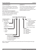
Section 1 General Information Model Numbers This manual covers the following models: SelfSelfContained Remote AirContained WaterCooled Air-Cooled Cooled IDF0300A IDF0300W ---IYF0300A IYF0300W ---IDT0420A IDT0420W ---IYT0420A IYT0420W ---IDT0450A IDT0450W ---IYT0450A IYT0450W ---IDT0500A IDT0500W IDT0500N IYT0500A IYT0500W IYT0500N IRT0500A IRT0500W ---IDF0600A IDF0600W IDF0600N IYF0600A IYF0600W IYF0600N IDT0620A IDT0620W ---IYT0620A IYT0620W ---IRT0620A ------IDP0620A ------IDF0900A IDF0900W IDF0900N IYF09
General Information Section 1 Top Air Discharge Kit The top air discharge kit can be used on select ice machine models. This kit directs warm exhaust air upward rather than out the side panels. LuminIce® II The LuminIce® growth inhibitor recirculates the air in the ice machine foodzone over a UV bulb. This process will inhibit the growth of common micro-organisms on all exposed foodzone surfaces. AuCS® Automatic Cleaning System This accessory reduces equipment cleaning expense.
Section 2 Installation Installation Installation Requirements Location Requirements • The ice machine and bin must be level. • Vent the ice machine and bin drains separately. • Bin drain termination must have an air gap. • The ice machine and bin must be sanitized after installation. • The drain line must contain a union or other suitable means of disconnection at the ice machine.
Installation Section 2 Minimum/Maximum Temperatures Minimum Air Maximum Air Model Temperature Temperature All Ice 35°F 110°F Machine Head 2°C 43°C Sections All Remote Condensers QuietQube Condensing Units CVDF0600 CVDF0900 CVDT1200 CVDF2100 CVDF1400 CVDF1800 12 -20°F -29°C 120°F 49°C -20°F -29°C 120°F 49°C -20°F -29°C 130°F 54°C Ice Machine Heat of Rejection Ice Machine Series IF0300 IT0420 IT0450 IT0500 IF0600 IT0620 IF0900 IT1200 IT1500 IT1900 Heat of Rejection Air Peak Conditioning 4600 5450 *
Section 2 Installation Clearance Requirements SelfSelfI0300 Contained Contained Air-Cooled Water‑Cooled Top/Sides *16" (40 cm) *8" (20 cm) Back *5" (13 cm) *5" (13 cm) SelfWater-Cooled IT0420 IT0450 Contained or Remote IT0500 IT0620 Air-Cooled Condenser Top/Sides 12" (31 cm) 8" (20 cm) Back 5" (13 cm) 5" (13 cm) IF0900 Top/Sides Back SelfSelfContained Contained Air-Cooled Water‑Cooled *8" (20 cm) *8" (20 cm) *5" (13 cm) *5" (13 cm) * Data marked with an asterisk is preliminary and subject to change - Mo
Installation Section 2 Condensing Unit Clearance Requirements Top/ Model Back Front Sides CVDF0600 CVDF0900 CVDT1200 0" 48" 48" CVDF1400 (0 cm*) (122 cm) (122 cm) CVDF1800 CVDF2100 * 61 cm (24") is recommended on top/sides for servicing Notic The ice machine must be protected if it will be subjected to temperatures below 32°F (0°C). Failure caused by exposure to freezing temperatures is not covered by the warranty.
Section 2 Installation Bin Installation Dispenser Installation NOTE: When using casters, the units must be tethered or secured to comply with all applicable codes. Swivel casters must be mounted on the front and rigid casters must be mounted on the rear. Lock the front casters after installation is complete. 1. Remove threaded plug from drain fitting. 2. Screw the leveling legs onto the bottom of the bin. 3. Screw the foot of each leg in as far as possible. 4. Move the bin into its final position. 5.
Installation Section 2 Electrical Requirements All electrical work, including wire routing and grounding, must conform to local, state and national electrical codes. The following precautions must be observed: • The ice machine must be grounded. • A separate fuse/circuit breaker (dedicated circuit) must be provided for each ice machine head section, condenser or condensing unit.
Section 2 Installation Maximum Breaker Size & Minimum Circuit Amperage Chart NOTE: Due to continuous product improvements, this information is for reference only. Please refer to the ice machine data plate to verify electrical data. Data plate information overrides information listed on this page.
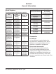
Installation Ice Machine IT1200 IT1500 IT1900 Section 2 Air-Cooled Water-Cooled Remote Condenser Voltage/ Maximum Minimum Maximum Minimum Maximum Minimum Fuse/ Fuse/ Phase/Cycle Fuse/ Circuit Circuit Circuit Circuit Circuit Circuit Amps Amps Amps Breaker Breaker Breaker 208-230/ 20 14.2 20 13.4 15 11.0 1/60 208-230/ 15 8.6 15 7.9 15 9.2 3/60 230/1/50 20 14.0 20 13.3 15 11.1 208-230/ 25 15.4 25 14.0 25 14.0 1/60 208-230/ 20 12.8 20 11.3 20 11.3 3/60 230/1/50 25 14.9 25 14.2 25 15.2 380-460/ ----15 *6.
Section 2 Installation QuietQube Head Sections Voltage/Phase/ Maximum Fuse/ Minimum Circuit Ice Machine Cycle Circuit Breaker Amps 115/1/60 15 amp --Ice Beverage Models 230/1/50 15 amp --All Non IB 115/1/60 15 amp 1.2 QuietQube 230/1/50 15 amp 1.2 Models Total Amps 1.2 1.2 ----- CVD Condensing Units Maximum Condensing Voltage/Phase/ Minimum Fuse/Circuit Unit Cycle Circuit Amps Breaker 208-230/1/60 15 amp *11.6 CVDF0600 208-230/3/60 15 amp *10.2 230/1/50 15 amp *10.2 208-230/1/60 20 amp *12.
Installation Section 2 Water Supply and Drain Line Sizing/Connections ,Caution Do not apply heat to water inlet valve or water drain fittings. Heating will damage the nonmetallic connector. Do not over tighten fittings. Two turns after hand tight is the maximum. • Local water conditions may require treatment of the water to inhibit scale formation, filter sediment, and remove chlorine odor and taste. • Connect ice making water inlet to potable water only. • Do not connect to hot water supply.
Section 2 Air Gap A greater than 1-inch air gap is built into the ice machine for back-flow prevention. This air gap exceeds NSF 12 requirements for back-flow prevention. This air gap is greater than 1" Cooling Tower Applications (Water-Cooled Models) A water cooling tower installation does not require modification of the ice machine. • Water pressure at the condenser cannot exceed 150 psig (1034 kPa). A special order unit is available that allows water pressure up to 350 psig (2413 kPa).
Installation Section 2 Remote Condenser and Condensing Unit Refrigeration System Installation Each ice machine head section ships from the factory with a refrigerant charge appropriate for the entire system operation. The serial tag on the ice machine indicates the refrigerant charge. Additional Refrigerant QuietQube® Ice Remote Condenser Line Set* Charge for 50' to 100' Machine (15 to 30 Meter) Line Sets IF0600C CVDF0600 1.
Section 2 Installation Remote Condenser Models Additional Amount of Refrigerant to Be Added to Ice Remote Nameplate Charge Machine Condenser for 50' to 100' (15 to 30 Meter) Line Sets IT0500N JCT0500 1.5 lbs - 680 g IF0600N JCT0900 1.5 lbs - 680 g IF0900N JCT0900 2 lbs - 907 g IT1200N JCT1200 2 lbs - 907 g IT1500N JCT1500 2 lbs - 907 g IT1900N JCT1500 2 lbs - 907 g Line Set Discharge Line Liquid Line Model RT 1/2 inch 5/16 inch iF0600N 20/35/50 13 mm 7.
Installation 4. Section 2 Add together the calculated rise, calculated drop, and horizontal distance to get the total calculated distance. If this total exceeds 150 feet (45 meters), move the condenser/ condensing unit to a new location and perform the calculations again. Maximum Line Set Distance Formula Step 1. Measured Rise (R) 35 feet (10.7 meters) Maximum _____ x 1.7 = _____ Calculated Rise Step 2. Measured Drop (D) 15 feet (4.5 meters) Maximum _____ x 6.6 = _____ Calculated Drop Step 3.
Section 2 When lengthening or shortening lines, follow good refrigeration practices, purge with nitrogen and insulate all tubing. Do not change the tube sizes. Evacuate the lines and place about 5 oz (145 grams) of vapor refrigerant charge in each line. 1. Remove the dust caps from the line set, condenser and ice machine. 2. Apply refrigeration oil to the threads on the quick-disconnect couplers before connecting them to the condenser. 3.
Installation Section 2 ALTERNATE CONNECTIONS AT CONDENSING UNIT SCHRADER VALVES VALVES MUST REMAIN CLOSED AND BE PROTECTED FROM HEAT WHEN BRAZING (WRAP WITH WET RAG) 26 CHECK VALVE CONDENSER Step 3 Pressure Test and Evacuate Line Set and CVD Condensing Unit. • Shutoff valves for the line set must remain closed until pressure testing and evacuation are complete.
Section 2 Installation Step 4 Open Valves for the Line Set and Receiver. You will not hear refrigerant flow when the valves are opened. Refrigerant will not flow until the ice machine is started and the solenoid valve opens. • All valve caps must be reinstalled, tightened and leak-checked to assure no refrigerant leakage exists. • Counterclockwise opens all valves: A. Open the shutoff valves for the suction and liquid lines. B. Open the receiver service valve until back seated (when used).
Installation Step 5 Leak-Check the Refrigeration System. A. Connect power to the ice machine head section - Do not connect power to the CVD condensing unit. B. Press the power switch and energize the ice machine for 60 seconds to equalize pressures. C. Disconnect power to the ice machine head section. D. Leak-check line set connections, S trap and all factory joints in head section and condensing unit. E. Connect power to the CVD condensing unit and allow system to pump down.
Section 2 Starting the Ice Machine Starting the ice machine and completing the Operational Checks are the responsibilities of the owner/operator. Adjustments and maintenance procedures outlined in this manual are not covered by the warranty. REMOVE ICE THICKNESS PROBE SHIPPING BRACKETS. Remove and discard shipping brackets before starting the ice machine. Step 1 Ice machine must be programmed refer to “Touch Screen Features” on page 31 for details.
Installation Design & Burst Pressure Design Pressure 600 psig - 4137 kPa Burst Pressure 2500 psig - 17237 kPa Head Pressure Control Valve Do not use a fan cycling control to try to maintain discharge pressure. Compressor failure will result. Any remote condenser connected to a Manitowoc Ice Machine must have the OEM head pressure control valve installed. Manitowoc will not accept substitute “off the shelf” head pressure control valves.
Section 3 Operation Lock/Unlock Screen Power Button Cleaning Button 4/17/2018 Alert Icon 3 Notification Icon 3 11:12 AM S Screen Locked or Unlocked LuminIce MAKING ICE Menu Icon i Service Locater Information Touch Screen Features The Indigo® control panel offers a series of pressure-sensitive buttons and an interactive touchscreen. Buttons Power Button: Provides On/Off functions for the ice machine. Lock/Unlock Button: Allows or prevents touchscreen navigation.
Operation Section 3 HOME SCREEN ICON DESCRIPTIONS Icon Description Home Screen Center portion of the screen displays the current condition of the ice machine - Making ice, bin full, program mode or machine off Alert 3 Message 3 Menu Alert icon with number of messages. Pressing this icon will display the alert log which will allow viewing and resetting of alerts Notification icon with quantity of messages.
Section 3 Operation Setup Wizard Screens will automatically advance after a selection is made or press the right arrow to advance one screen, press left arrow to go back one screen. All settings can be accessed and changed without the wizard by using menu screen navigation. Setup Press ON/ OFF Button Enter Model Number Select Language Start Wizard Accessory Detection USB Setup Configure Date and Time Formats Set Time Set Date Units Brightness Description On/Off button is used to start/stop ice making.
Operation Section 3 Menu Screen Navigation Select SETTINGS Icon from the Home Screen to access Main Menu screen.
Section 3 Operation Ice Making Sequence of Operation Control Board Timers The power button must be depressed and the water curtain/ice dampers must be in place on the evaporator before the ice machine will start. The control board has the following nonadjustable timers: • The ice machine control board will set its own install date after 100 freeze and harvest cycles. • The ice machine is locked into the freeze cycle for 6 minutes before a harvest cycle can be initiated.
Operation Safe Operation Mode Allows the ice machine to operate up to 72 hours if the ice thickness probe and/or water level probe sensors fail. • When the control board starts the safe mode, an alert is flashed on the display to notify the end-user they have a production problem. • The control board automatically initiates and monitors the safe mode. The control will automatically exit the safe mode if a normal signal is received from the input.
Section 3 Operation Minimum/Maximum Slab Weight Ice Thickness Check Adjust ice thickness to meet chart specifications. Minimum Maximum Ice Weight Ice Weight Model Per Cycle Per Cycle lbs lbs Grams Grams 2.40 lbs 2.80 lbs IF0300 1089 grams 1270 grams IT0420 IT0450 3.40 lbs 3.90 lbs IT0520 IT0620 1542 grams 1769 grams 4.60 lbs 5.20 lbs IT0500 2087 grams 2359 grams 4.12 lbs 4.75 lbs IF0600 1869 grams 2155 grams 5.75 lbs 6.50 lbs IBF0820 2608 grams 2948 grams 6.20 lbs 7.
Operation Section 3 THIS PAGE INTENTIONALLY LEFT BLANK 38 Part Number: 000014141 Rev 03 2/18
Section 4 Maintenance Cleaning and Sanitizing General You are responsible for maintaining the ice machine in accordance with the instructions in this manual. Maintenance procedures are not covered by the warranty. Clean and sanitize the ice machine every six months for efficient operation. If the ice machine requires more frequent cleaning and sanitizing, consult a qualified service company to test the water quality and recommend appropriate water treatment.
Maintenance Section 4 Exterior Cleaning Clean the area around the ice machine as often as necessary to maintain cleanliness and efficient operation. Wipe surfaces with a damp cloth rinsed in water to remove dust and dirt from the outside of the ice machine. If a greasy residue persists, use a damp cloth rinsed in a mild dish soap and water solution. Wipe dry with a clean, soft cloth. The exterior panels have a clear coating that is stain resistant and easy to clean.
Section 4 Maintenance Step 2 Remove all ice from the bin/ dispenser. Step 3 Press the Clean button and select “Turn off when complete”. Water will flow through the water dump valve and down the drain. Wait approximately 1 minute until the water trough refills and the display indicates Add Chemical. Add the proper amount of ice machine cleaner to the water trough by pouring between the water curtain and evaporator, then confirm the chemical was added.
Maintenance Section 4 Step 8 While components are soaking, use half of the cleaner/water solution to clean all food zone surfaces of the ice machine and bin (or dispenser). Use a nylon brush or cloth to thoroughly clean the following ice machine areas: • Side walls • Base (area above water trough) • Evaporator plastic parts - including top, bottom and sides • Bin or dispenser Rinse all areas thoroughly with clean water. SANITIZING PROCEDURE Step 9 Mix a solution of sanitizer and lukewarm water.
Section 4 Maintenance Parts Removal for Cleaning/Sanitizing Single evaporator is shown; Each evaporator will have a distribution tube and water curtain/damper. A. Remove the water curtain(s) • Gently flex the curtain in the center and remove it from the right side. • Slide the left pin out. B. Remove the ice thickness probe • Compress the hinge pin on the top of the ice thickness probe. • Pivot the ice thickness probe to disengage one pin then the other.
Maintenance Section 4 Preventative Maintenance Cleaning Procedure This procedure cleans all components in the water flow path, and is used to clean the ice machine between the bi-yearly cleaning/sanitizing procedure. Ice machine cleaner is used to remove lime scale and mineral deposits. Ice machine sanitizer disinfects and removes algae and slime. NOTE: Although not required and dependent on your installation, removing the ice machine top cover may allow easier access.
Section 4 Maintenance Cleaning the Air Filter and Condenser Removal from Service/Winterization The washable filter on self-contained ice machines is designed to catch dust, dirt, lint and grease. Clean the filter once a month with mild soap and water. A dirty condenser restricts airflow, resulting in excessively high operating temperatures. This reduces ice production and shortens component life. All Models 1. Clean and sanitize the ice machine. 2.
Maintenance Section 4 THIS PAGE INTENTIONALLY LEFT BLANK 46 Part Number: 000014141 Rev 03 2/18
Section 5 Troubleshooting Before Calling for Service Checklist If a problem arises during operation of your ice machine, follow the checklist below before calling service. Routine adjustments and maintenance procedures are not covered by the warranty. Problem Possible Cause To Correct Ice machine does not No electrical power to the ice Replace the fuse/reset the operate. machine and/or condensing breaker/turn on the main unit. switch. High pressure cutout tripping. Clean condenser coil.
Troubleshooting Section 5 Problem Possible Cause Ice machine does not cycle The six-minute freeze time into harvest mode. lock-in has not expired yet. Ice thickness probe is dirty. To Correct Wait for the freeze lock-in to expire. Clean and sanitize the ice machine. (See page 40) Ice thickness probe is Connect the probe to the disconnected. control board. Ice thickness probe is out of Adjust the ice thickness probe. adjustment.
Section 5 Problem Low ice capacity. Troubleshooting Possible Cause Water inlet valve filter screen is dirty. Incoming water supply is shut off. Water inlet valve stuck open or leaking. To Correct Remove the water inlet valve and clean the filter screen. Open the water service valve. Press the power button and turn off the ice machine, if water continues to enter water trough, replace the water inlet valve. The condenser is dirty. Clean the condenser.
Troubleshooting Section 5 THIS PAGE INTENTIONALLY LEFT BLANK 50 Part Number: 000014141 Rev 03 2/18
MANITOWOC ICE ICE MACHINE DIVISION 2110 SOUTH 26TH STREET MANITOWOC, WI 54220 800-545-5720 WWW.MANITOWOCICE.COM WWW.WELBILT.COM Welbilt provides the world’s top chefs, and premier chain operators or growing independents with industry leading equipment and solutions. Our cuttingedge designs and lean manufacturing tactics are powered by deep knowledge, operator insights, and culinary expertise. All of our products are backed by KitchenCare® – our aftermarket, repair, and parts service.