
Service Manual

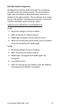


Table Of Contents
- General Information
- Model Numbers
- Installation
- Maintenance
- Troubleshooting
- Component Check Procedures
- Electrical Components
- Main Fuse
- ICE/OFF/CLEAN Toggle Switch
- Float Switch
- Ice Damper and Hall Effect Switches
- Selector Switch
- Dispense Lever Activated
- Touchless Sensor Activated
- Dispense Switch
- Touchless Sensor
- High Pressure Cutout Control
- Fan Cycle Control
- Low Pressure Cutout (LPCO) Control
- Compressor Electrical Diagnostics
- Diagnosing Start Components
- Refrigerant Recovery/Evacuation
- System Contamination Clean-Up
- Electrical Components
- Component Specifications
- Charts
- Diagrams

Part Number 000015432 4/18 77
SELECTOR SWITCH
FUNCTION
Selects product dispensed. Ice, Water or Ice and Water.
CHECK
DISPENSE LEVER ACTIVATED
Step 1 Verify line voltage is present at control board
wires #20 & #22. Note - If a blue indicator light is energized
on the touch pad, the control board has line voltage.
Step 2 Depress each selection on the touch pad.
• 1 or more LEDs do not energize/de-energize when a
selection is pressed - Replace touch pad
• Each touch pad LED energizes/de-energizes as
selections are pressed - Go to next step
Step 3 Isolate and ohm the ice dispense switch (Wires
#59 & #60). The selector switch closes when depressed
and opens when released.
• Switch does not close/open when the switch is
pressed/released - Replace switch
• Switch closes/opens as the switch is pressed/released
- Go to next step
Step 4 Reconnect dispense switch and test both relays
for line voltage:
• Wires #58 & #54 = Ice Dispense Motor
• Wires #52 & #56 = Water Solenoid
• Replace wiring, component or control board as
required.