CM050 CM Model Ice Machines This manual is updated as new STH003 Information and models are released 06/06 Visit our website for the latest manual: ©Manitowoc Ice, Inc. www.compact-ice.
Safety Notices When using or servicing these Ice Machines, be sure to pay close attention to the safety notices in this handbook. Disregarding the notices may lead to serious injury and/or damage to the ice machine. Throughout this handbook, you will see the following types of safety notices: WARNING Text in a Warning box alerts you to a potential personal injury situation. Be sure to read the Warning statement before proceeding, and work carefully.
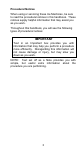
Procedural Notices When using or servicing these Ice Machines, be sure to read the procedural notices in this handbook. These notices supply helpful information that may assist you as you work. Throughout this handbook, you will see the following types of procedural notices: IMPORTANT Text in an Important box provides you with information that may help you perform a procedure more efficiently. Disregarding this information will not cause damage or injury, but may slow you down as you work.
Read These Before Proceeding: CAUTION Proper installation, care and maintenance are essential for maximum ice production and trouble free operation of your Compact Ice Machine. Read and understand this manual. If you encounter problems not covered by this manual, do not proceed, contact Manitowoc Ice, Inc. We will be happy to provide assistance. IMPORTANT Routine adjustments and maintenance procedures outlined in this manual are not covered by the warranty.
TABLE OF CONTENTS GENERAL INFORMATION............................. 7 MODEL NUMBERS .....................................7 ACCESSORIES...........................................8 MODEL/SERIAL NUMBER LOCATION .......9 OWNER WARRANTY REGISTRATION........... 9 INSTALLATION .......................................... 13 LOCATION OF ICE MACHINE ..................13 ICE MACHINE HEAT OF REJECTION ......14 LEVELING THE ICE MACHINE ................15 WATER SERVICE/DRAINS .......................
HOT GAS VALVE..................................... 52 BIN THERMOSTAT.................................. 55 ICE PRODUCTION CHECK ...................... 57 ADJUSTING CUBE WEIGHT ................... 58 LIQUID LINE THERMISTOR .................... 59 TOTAL SYSTEM REFRIGERATION CHARGE.................................................. 61 COMPONENT SPECIFICATIONS AND CHECK PROCEDURES ............................................ 62 MAIN FUSE .............................................
GENERAL INFORMATION MODEL NUMBERS This manual covers the following models: CMS050A004 WARNING An ice machine contains high voltage electricity and refrigerant charge. Repairs are to be performed by properly trained refrigeration technicians aware of the dangers of dealing with high voltage electricity and refrigerant under pressure.
ACCESSORIES Visit our website at: www.compact-ice.com for these optional accessories: LEGS Four inch adjustable legs are available. DRAIN PUMP Pumps waste water from ice machine to drain. MANITOWOC ICE MACHINE CLEANER AND SANITIZER These are the only cleaner and sanitizer approved for use with Compact products.
MODEL/SERIAL NUMBER LOCATION The model and serial numbers are required when requesting information from your local Compact retailer or Compact Ice at 800-235-9698.
OWNER WARRANTY REGISTRATION CARD GENERAL The packet containing this manual also includes warranty information. Warranty coverage begins the day you purchase your new ice machine. Compact CM Series Limited Ice Machine Warranty Subject to the exclusions and limitations below, Manitowoc Ice, Inc. (“Manitowoc Ice”) warrants this CM Series Ice Machine (the “Product”) against defects in material or workmanship as follows: 1. Labor.
This limited warranty only applies to the original Purchaser of the Product and is not transferable. This limited warranty is valid only in the United States.
IN NO EVENT SHALL MANITOWOC ICE OR ANY OF ITS AFFILIATES BE LIABLE TO THE PURCHASER OR ANY OTHER PERSON FOR ANY INCIDENTIAL, CONSEQUENTIAL OR SPECIAL DAMAGES OF ANY KIND ARISING FROM OR IN ANY MANNER CONNECTED WITH THE PRODUCT, ANY BREACH OF THIS LIMITED WARRANTY, OR ANY OTHER CAUSE. Some states do not allow the exclusion or limitation of incidental or consequential damages, so the above limitation or exclusion may not apply to you.
INSTALLATION LOCATION OF ICE MACHINE The location selected for the ice machine must meet the following criteria. If any of these criteria are not met, select another location. • The location must be indoors. • The location must be free of airborne and other contaminants. • Air temperature: must be at least 50ºF (10ºC) but must not exceed 110ºF (43ºC). • The location must not be near heat-generating equipment or in direct sunlight.
ICE MACHINE HEAT OF REJECTION Heat of Rejection* Air Conditioning** Peak 1,145 2,300 * B.T.U./Hour ** Because the heat of rejection varies during the ice making cycle, the figure shown is an average. Ice machines, like other refrigeration equipment, reject heat through the condenser. It is helpful to know the amount of heat rejected by the ice machine when sizing air conditioning equipment where self-contained air-cooled ice machines are installed.
LEVELING THE ICE MACHINE After moving the ice machine into the installation location, it must be leveled for proper operation. Follow these steps to level the ice machine: 1. 2. 3. 4. Use a level to check the levelness of the ice machine from front to back and from side to side. If the ice machine is not level, adjust the leveling glides or legs on each corner of the base of the ice machine as necessary. Check the levelness of the ice machine after each adjustment.
WATER SERVICE/DRAINS WATER SUPPLY Local water conditions may require treatment of the water to inhibit scale formation, filter sediment, and remove chlorine odor and taste. IMPORTANT If you are installing a Manitowoc water filter system, refer to the Installation Instructions supplied with the filter system for ice making water inlet connections. WATER INLET LINES Follow these guidelines to install water inlet lines: • • • • Do not connect the ice machine to a hot water supply.
----- ----- Drain Pump 1/4" (.64 cm) min. inside diameter 1/4" (.64 cm) ID Copper Tubing 3/8" (.96 cm) 3/8" (.96 cm) ID Hose minimum 3/4" (1.9 cm) 3/4" (1.9 cm) minimum inside Hose Barb diameter Tubing Size Up to Ice Machine Fitting Ice Machine Fitting Note: If air temperature is less than 60 F (15.5 C) water temperature must be equal or greater than 50°F (10°C). ----- 20 psi (1.38 bar) Min 80 psi (5.5 bar) Max -----. 35°F (1.7°C) Min. 90°F (32.°C) Max.
ELECTRICAL REQUIREMENTS VOLTAGE The maximum allowable voltage variation is ±10% of the rated voltage on the ice machine model/serial number plate at start-up (when the electrical load is highest). • A qualified electrician must determine proper wire size dependent upon location, materials used and length of run (minimum circuit ampacity can be used to help select the wire size).
COMPONENT IDENTIFICATION Bin Light Control Panel Water Shutters Water Trough Evaporator Compartment Bin Bin Thermostat Adjustment Grill Water Pu mp Electrical Drain Pu mp (Optio nal) Drain Refrig erat io n Comp ression Water In let 19
Water Pum p Evaporator Water Shutter Assembly Water Supply Line Note: Evap orator removed for clarity Spray Bar Spray Nozzles Evaporator Bucket Water Shutters Control Board 20
OPERATIONAL CHECKS Routine adjustments and maintenance procedures outlined in this manual are not covered by the warranty WATER INLET VALVE The water inlet valve energizes in the harvest cycle. The water level will rise and flow out the overflow tube and down the drain. Verify the overflow tube is in place in the water trough. The water level is not adjustable. BIN THERMOSTAT ADJUSTMENT The bin thermostat stops the ice machine when the bin is full.
SAFETY TIMERS The control board has the following nonadjustable safety timers: • Initial cycle is 5 minutes longer than subsequent cycles. • The ice machine is locked into the freeze cycle for 10 minutes (15 minutes initial cycle) before a harvest cycle can be initiated. • The maximum freeze time is 120 minutes at which time the control board automatically initiates a harvest cycle (step 4).
MAINTENANCE ICE MACHINE INSPECTION Check all water fittings and lines for leaks. Also, make sure the refrigeration tubing is not rubbing or vibrating against other tubing, panels, etc. Do not put anything (boxes, etc.) in front of the ice machine. There must be adequate airflow through and around the ice machine to maximize ice production and ensure long component life. EXTERIOR CLEANING Clean the area around the ice machine as often as necessary to maintain cleanliness and efficient operation.
AIR-COOLED CONDENSER A dirty condenser restricts airflow, resulting in excessively high operating temperatures. This reduces ice production and shortens component life. Clean the condenser at least every six months. Follow the steps below. WARNING The condenser fins are sharp. Use care when cleaning them. 1. 2. 3. 4. 5. The washable aluminum filter on self-contained air-cooled ice machines is designed to catch dust, dirt, lint and grease. This helps keep the condenser clean.
INTERIOR CLEANING AND SANITIZING CAUTION Use only Manitowoc approved Ice Machine Cleaner (part number 000000084 clear metal safe ice machine cleaner) and Sanitizer (part number 94-0565-3). It is a violation of Federal law to use these solutions in a manner inconsistent with their labeling. Read and understand all labels printed on bottles before use. CAUTION Do not mix Ice Machine Cleaner and Sanitizer solutions together.
INTERIOR CLEANING AND SANITIZING GENERAL Perform an In Place Cleaning/Sanitizing procedure monthly and a Cleaning/Sanitizing procedure every 12 months for efficient operation. If the ice machine requires more frequent cleaning and sanitizing, consult a qualified service company to test the water quality and recommend appropriate water treatment. An extremely dirty ice machine must be taken apart for cleaning and sanitizing.
Step 2 Press the clean switch. The ice machine will initiate a 2 minute harvest to remove any remaining ice from the evaporator. Step 3 Remove all ice from the bin. Step 4 Wait 3 minutes until the Clean light flashes, then add the prepared Manitowoc Cleaner by lifting the water shutters and pouring directly into the spray area. Step 5 The ice machine will automatically time out a ten minute cleaning cycle, followed by eight rinse cycles, and stop.
CLEANING PROCEDURE Ice machine cleaner is used to remove lime scale and other mineral deposits. Ice machine sanitizer disinfects and removes algae and slime. NOTE: All ice must be removed from the bin. Step 1 Prepare 4 oz (1/2 cup) of undiluted Manitowoc Ice Machine Cleaner (part number 000000084 only) in a container that will fit easily under the lifted water shutters. Refer to page 3-1 to identify the water shutters. Step 2 Press the Clean switch.
Step 7 Take all removed components to a sink for cleaning. Use 1/2 of the cleaner/water mixture to clean all components. The cleaner solution will foam when it contacts lime scale and mineral deposits; once the foaming stops, use a soft-bristle nylon brush, sponge or cloth (NOT a wire brush) to carefully clean the parts. Disassemble the spray bar, remove nozzles and inserts and soak for 5 minutes. For heavily scaled parts, soak in solution for 15 – 20 minutes. Rinse all components with clean water.
Step 15 Wait 3 minutes until the Clean light flashes, then add the prepared Manitowoc Sanitizer by lifting the water shutters and pouring directly into the spray area. The ice machine will automatically time out a ten minute sanitizing cycle, followed by eight rinse cycles, and stop. The Clean light will turn off to indicate the sanitizing cycle is complete. This entire cycle lasts approximately 30 minutes.
REMOVAL OF PARTS FOR CLEANING AND SANITIZING TOP COVER 1. Remove two back screws. 2. Slide back and lift cover off. WARNING Disconnect electric power to the ice machine at the electric switch box before proceeding.
WATER SHUTTERS The water shutter is designed to keep the spraying water from escaping the evaporator compartment. To remove just the water shutters: 1. Grasp one end of the water shutter and lift up. 2. Pivot water shutter and disengage remaining end. 3. To re-install into ice machine, grasp one end of the water shutters, install one end, pivot the opposite end and pull down into position. Make sure tabs are secure in grooves. To remove water shutter assembly: 1.
ICE CHUTE The ice chute is positioned over the spray nozzles and allows the ice to easily fall into the bin. It must be firmly positioned over the spray bar, with the front edge inside the water trough. Spray nozzles must align with the spray holes or spray water will fall into the bin. 1. 2. Grab protruding spray hole on one end and lift up and remove. To re-install ice chute, grasp protruding spray hole and position over Water Distribution Assembly.
SUMP DRAIN OVERFLOW TUBE 1. Remove clamp. 2. Pull down to remove overflow tube and tubing as an assembly. The sump trough water will drain into the bin. 3. Remove overflow tube from vinyl tubing by pulling.
WATER TROUGH 1. Depress tabs on right and left side of the water trough. 2. Allow front of water trough to drop as you pull forward to disengage the rear pins.
SPRAY BAR, WATER PUMP AND HOSE WARNING Disconnect the electric power to the ice machine at the electric service switch box and turn off the water supply before proceeding. Remove spray bar clamp and spray bar. 1. Grasp pump and pull straight down until water pump disengages and electrical connector is visible. 2. Disconnect the electrical connector. 3. Remove the water pump from ice machine. 4. Remove clamp from hose to remove from pump. 5.
SPRAY BAR DISASSEMBLY The spray bar supplies water to the individual ice making cups. Water from the water pump sprays through the nozzles, located on the upper portion of the tubes. 1. Grasp one end of the spray bar, lift up and remove from seat formed in evaporator bucket. 2. Remove clamp on water inlet tubing by grasping both ears on clip and separating. 3. Apply food grade lubricant to ease re-assembly of spray bar components when necessary. 4.
REMOVAL FROM SERVICE/LONG TERM STORAGE/WINTERIZATION GENERAL Special precautions must be taken if the ice machine is to be removed from service for an extended period of time or exposed to ambient temperatures of 32°F (0°C) or below. CAUTION If water is allowed to remain in the ice machine in freezing temperatures, severe damage to some components could result. Damage of this nature is not covered by the warranty. Follow the applicable procedure below. SELF-CONTAINED AIR-COOLED ICE MACHINES 1.
ICE MAKING SEQUENCE OF OPERATION Depending on ambient conditions and cold water supply temperature, the ice making process will take approximately 30 minutes. 1. 2. 3. 4. 5. Initial Start-Up or Start-Up After Automatic Shut-Off — Water Fill Before the compressor starts, the water inlet valve will energize to purge old water from the system for about 3 minutes. Refrigeration System Start-Up The compressor starts after the Water Fill cycle and remains on throughout the Freeze and Harvest cycles.
5. Auto-Shut-Off 4. Harvest Cycle 3. Freeze Cycle 1. WaterFill 2.
TROUBLESHOOTING DIAGNOSING AN ICE MACHINE THAT WILL NOT RUN WARNING High (line) voltage is applied to the control board (terminals #20 and #21) at all times. Removing control board fuse or moving the toggle switch to OFF will not remove the power supplied to the control board. 1. 2. 3. 4. Verify primary voltage is supplied to ice machine. Verify that the fuse or circuit breaker is closed and the ice machine is plugged into a receptacle. Verify control board fuse is OK.
5. 6. 7. 8. Verify the “Power” switch functions properly. • If the red control board light is energized and depressing the “Power” switch does not energize the green “Power” light, check the interconnecting wire, then replace the interface board. Verify the bin thermostat functions properly. • The green “Power” light will be energized and the ice machine will function in the “Clean” cycle with the bin thermostat is open.
ICE MACHINE WILL NOT HARVEST 1. Verify cubes are present in evaporator and freeze time exceeds freeze chart cycle time. • Initial freeze cycle after resetting at toggle switch will be 5 minutes longer than chart time (refer to Sequence of Operation). • 2. Verify control board is not set for additional freeze time to fill out the ice cubes, see cube weight adjustment. Observe control board light: • Steady light indicates thermistor operation is normal.
ICE QUALITY IS POOR – CUBES ARE SHALLOW, INCOMPLETE OR WHITE Problem Cause Ice machine is dirty • Clean and sanitize the ice machine Water filtration is poor • Replace the filter Water softener is working improperly (if applicable) • Repair the water softener Poor incoming water quality • Contact a qualified company to test the quality of the incoming water and make appropriate filter recommendations Water escaping from sump during freeze cycle • Check standpipe and drain • Check for water tracking out of w
FREEZE CYCLE IS LONG, LOW ICE PRODUCTION Problem Cause Water temperature is too high • Connect to a cold water supply, verify check valves in faucets and other equipment are functioning correctly Dirty Condenser • Clean condenser High air temperature entering condenser • Air temperature must not exceed 120°F (39°C) Water inlet valve filter screen is dirty • Remove the water inlet valve and clean the filter screen Water inlet valve stuck open or leaking • Turn off ice machine, if water continues to enter ice
ICE MACHINE RUNS & NO ICE IS PRODUCED Problem Cause No water to ice machine • Correct water supply Incorrect incoming water pressure • Water pressure must be 20-80 psi (1.4-5.
ANALYZING DISCHARGE PRESSURE 1. Determine the ice machine operating conditions: Air temp. entering condenser ______ Air temp. around ice machine ______ Water temp. entering sump trough______ 2. Refer to Cycle Times/24 Hour Ice Production/Refrigeration Pressure Chart for ice machine being checked. Use the operating conditions determined in Step 1 to find the published normal discharge pressures. 3. Freeze Cycle ______ Harvest Cycle______ Perform an actual discharge pressure check.
DISCHARGE PRESSURE HIGH CHECKLIST Problem • Cause Improper Installation • Refer to “Installation/Visual Inspection Checklist” Restricted Condenser Air Flow • High inlet air temperature • Condenser discharge air re-circulation • Dirty condenser fins • Defective fan motor Improper Refrigerant Charge • Overcharged • Non-condensable in system • Wrong type of refrigerant Other • Non-Manitowoc components in system • High side refrigerant lines/component restricted (before mid-condenser) FREEZE CYCLE DISCHARGE PRE
ANALYZING SUCTION PRESSURE The suction pressure gradually drops throughout the freeze cycle. The actual suction pressure (and drop rate) changes as the air and water temperature entering the ice machine changes. These variables also determine the freeze cycle times. To analyze and identify the proper suction pressure drop throughout the freeze cycle, compare the published suction pressure to the published freeze cycle time. NOTE: Analyze discharge pressure before analyzing suction pressure.
PROCEDURE Step . 1. Determine the ice machine operating conditions. 2A. Refer to “Cycle Time” and “Operating Pressure” charts for ice machine model being checked. Using operating conditions from Step 1, determine published freeze cycle time and published freeze cycle suction pressure. 2B. Compare the published freeze cycle time and published freeze cycle suction pressure. Develop a chart. Air temp. entering condenser: 90°F/32.2°C Air temp. around ice machine: 80°F/26.7°C Water temp.
SUCTION PRESSURE HIGH CHECKLIST Problem • Cause Improper Installation • Refer to “Installation/Visual Inspection Checklist” Discharge Pressure • Discharge pressure is too high, and is affecting suction pressure, refer to “Freeze Cycle Discharge Pressure High Checklist” Improper Refrigerant Charge • Overcharged • Wrong type of refrigerant • Non Condensable in system Other • Non-Manitowoc components in system • Hot gas valve leaking • Defective compressor • Water inlet valve leaking SUCTION PRESSURE LOW CHECK
HOT GAS VALVE General The hot gas valve is an electrically operated valve that opens when energized, and closes when de-energized. Normal Operation The valve is de-energized (closed) during the freeze cycle and energized (open) during the harvest cycle. The valve is positioned between the receiver and the evaporator and performs two functions: 1. Prevents refrigerant from entering the evaporator during the freeze cycle. The hot gas valve is not used during the freeze cycle.
HOT GAS VALVE ANALYSIS The valve can fail in two positions: • Valve will not open in the harvest cycle. • Valve remains open during the freeze cycle. Valve will not open in the harvest cycle Although the circuit board has initiated a harvest cycle, the evaporator temperature remains unchanged from the freeze cycle. Valve remains open in the freeze cycle: Symptoms are dependent on the amount of leakage in the freeze cycle. A small amount of leakage will cause increased freeze cycle times.
EXAMPLES OF HOT GAS VALVE INLET/COMPRESSOR DISCHARGE LINE TEMPERATURE COMPARISON Findings Comments The inlet of the hot gas valve is cool enough to touch and the compressor discharge line is hot. The inlet of the hot gas valve is hot and approaches the temperature of a hot compressor discharge line.
BIN THERMOSTAT Function The bin thermostat stops the ice machine when the bin is full. The level of ice in the ice storage bin controls the ice machine shut-off. When the bin is full, ice cubes contact the bin thermostat bulb holder, which cools down and opens the bin thermostat to stop the ice machine. The ice machine remains off until enough ice has been removed from the bin. This causes the thermostat bulb holder to warm and closes the bin thermostat, restarting the ice machine.
Check Procedure WARNING High (line) voltage is applied to the control board (terminals #20 and #21) at all times. Removing the control board fuse or depressing the power button will not remove the power supplied to the control board. WARNING Disconnect electrical power to the entire ice machine before proceeding. 1. 2. 3. Verify the capillary tube is inserted correctly in the bulb holder (17” 43 cm). Remove the 2 bottom front panels to access the bin thermostat.
ICE PRODUCTION CHECK The amount of ice a machine produces directly relates to the operating water and air temperatures. This means an ice machine with a 70°F (21.2°C) ambient temperature and 50°F (10.0°C) water produces more ice than the same ice machine with 90°F (32.2°C) ambient and 70°F (21.2°C) water. 1. Determine the ice machine operating conditions: 2. 3.
ADJUSTING CUBE WEIGHT The cube weight can be increased from the factory setting by adjusting the finish time. Additional finishing time check: Press and hold the power button for 5 seconds. • Count the flashes on the Automatic Ice Making light. The light will flash once for each additional minute of freeze cycle time. Adjusting Finishing Time Adjust in 1-minute increments and allow the ice machine to run several freeze/harvest cycles, and then inspect the ice cubes.
LIQUID LINE THERMISTOR Function The liquid line thermistor senses the refrigeration system liquid line temperature. This is used in conjunction with the control board to determine the length of the freeze and harvest cycles. Specifications 10,000 Ohms ± 2% at 25°C (77°F) CAUTION Use only Manitowoc thermistors. Check Procedure Verify that the thermistor resistance is accurate and corresponding to the high and low temperature ranges. 1. 2. Disconnect the thermistor at the control board.
TEMPERATURE/RESISTANCE CHART As the temperature rises at the thermistor block, the resistance drops. IMPORTANT If the ohmmeter reads “OL,” check the scale setting on the meter before assuming the thermistor is bad. SM50 Resistance Chart Temperature of Thermistor Resistance °C °F K Ohms (x 1000) 15.6° - 21.1° 60° - 70° 15.31 - 11.88 21.1° - 26.7° 70° - 80° 11.88 - 9.29 26.7° - 32.2° 80° - 90° 9.29 - 7.33 32.2° - 37.8° 90° - 100° 7.33 - 5.82 37.8° - 43.3° 100° - 110° 5.82 - 4.66 43.3° - 48.9° 110° - 120° 4.
TOTAL SYSTEM REFRIGERATION CHARGE IMPORTANT This information is for reference only. Refer to the ice machine serial number tag to verify the system charge. Serial plate information overrides information listed on this page.
COMPONENT SPECIFICATIONS AND CHECK PROCEDURES MAIN FUSE Function The control board fuse stops ice machine operation if electrical components fail causing high amp draw. Specifications CM50 Volt Amp 250 10 Check Procedure WARNING High (line) voltage is applied to the control board at all times. Removing the control board fuse or moving the toggle switch to OFF will not remove the power supplied to the control board. 1. If the bin switch light is on with the ice damper closed, the fuse is good.
COMPRESSOR ELECTRICAL DIAGNOSTICS The compressor does not start or will trip repeatedly on overload. CHECK RESISTANCE (OHM) VALUES NOTE: Compressor windings can have very low ohm values. Use a properly calibrated meter. Perform the resistance test after the compressor cools. The compressor dome should be cool enough to touch (below 120°F/49°C) to assure that the overload is closed and the resistance readings will be accurate. SINGLE PHASE COMPRESSORS 1.
COMPRESSOR DRAWING LOCKED ROTOR The two likely causes of this are: • Defective starting component • Mechanically seized compressor To determine which you have: • Install high and low side gauges. • Try to start the compressor. • Watch the pressures closely. If the pressures do not move, the compressor is seized. Replace the compressor. If the pressures move, the compressor is turning slowly and is not seized. Check the capacitors and relay.
DIAGNOSING START COMPONENTS: If the compressor attempts to start, or hums and trips the overload protector, check the start components before replacing the compressor. CAPACITOR Visual evidence of capacitor failure can include a bulged terminal end or a ruptured membrane. Do not assume a capacitor is good if no visual evidence is present. A good test is to install a known good substitute capacitor. Use a capacitor tester when checking a suspect capacitor.
CYCLE TIMES, 24 HR ICE PRODUCTION AND REFRIGERANT PRESSURE CHARTS These charts are used as guidelines to verify correct ice machine operation. Accurate collection of data is essential to obtain the correct diagnosis. • Refer to “OPERATIONAL ANALYSIS CHART” for the list of data that must be collected for refrigeration diagnostics.
NOTE: THESE CHARACTERISTICS MAY VARY DEPENDING ON OPERATING CONDITIONS. Cycle Times Freeze Time + Harvest Time = Cycle Time AIR TEMP. ENTERING CONDENSER °F/°C 70/21.1 80/26.7 90/32.2 100/37.8 110/43.3 Times in minutes HARVEST FREEZE TIME TIME WATER TEMPERATURE °F/°C 50/10.0 70/21.1 90/32.2 15.6-17.8 15.3-17.4 15.6-17.8 16.6-18.9 17.0-19.4 17.4-19.8 1.0-3.5 17.4-19.8 19.1-21.7 18.2-20.7 19.2-22.1 19.8-22.7 22.4-25.4 24.9-28.2 25.7-29.1 31.4-35.5 24 Hour Ice Production AIR TEMP.
REFRIGERANT DEFINITIONS Recover To remove refrigerant, in any condition, from a system and store it in an external container, without necessarily testing or processing it in any way. Recycle To clean refrigerant for re-use by oil separation and single or multiple passes through devices, such as replaceable core filter-driers, which reduce moisture, acidity and particulate matter. This term usually applies to procedures implemented at the field job site or at a local service shop.
REFRIGERANT RE-USE POLICY Manitowoc recognizes and supports the need for proper handling, re-use, and disposal of, CFC and HCFC refrigerants. Manitowoc service procedures require recapturing refrigerants, not venting them to the atmosphere. It is not necessary, in or out of warranty, to reduce or compromise the quality and reliability of your customers’ products to achieve this. IMPORTANT Manitowoc Ice, Inc. assumes no responsibility for use of contaminated refrigerant.
4. 5. Recovered refrigerant must come from a “contaminant-free” system. To decide whether the system is contaminant free, consider: • Type(s) of previous failure(s) • Whether the system was cleaned, evacuated and recharged properly following failure(s) • Whether the system has been contaminated by this failure • Compressor motor burnouts and improper past service prevent refrigerant re-use. • Refer to “System Contamination Cleanup” to test for contamination.
Refrigerant Recovery/Evacuation/Charging Do not purge refrigerant to the atmosphere. Capture refrigerant using recovery equipment. Follow the manufacturer’s recommendations. Install and uninstall your manifold gauge set correctly to prevent refrigerant loss. IMPORTANT Manitowoc Ice, Inc. assumes no responsibility for the use of contaminated refrigerant. Damage resulting from the use of contaminated refrigerant is the sole responsibility of the servicing company.
IMPORTANT Manifold gauges must be removed properly to ensure that no refrigerant contamination or loss occurs. A quick disconnect is required for the high side connection. Recovery/Evacuation 1. Place the toggle switch in the OFF position. 2. Install manifold gauges, charging scale, and recovery unit or two-stage vacuum pump. 3. Open the high and low side valves on manifold gauges. 4. Perform recovery or evacuation: A.
Charging Procedures IMPORTANT The charge is critical on all Manitowoc ice machines. Use a scale to ensure the proper charge is installed. A quick disconnect is required for the high side connection 1. 2. 3. 4. 5. 6. 7. 8. Be sure the toggle switch is in the OFF position. Close the vacuum pump valve and the low side manifold gauge valve. Open the high side manifold gauge valve. Using a digital scale add the proper refrigerant charge (shown on nameplate) through the high side.
9. Make sure that all refrigerant in the charging hose is drawn into the ice machine before disconnecting the manifold gauge set. A. Drain the water from the sump trough. B. Run the ice machine in the freeze cycle for 5 minutes. C. Remove the high side hose with the quick disconnect. D. Open the high and low side valves on the manifold gauge set. Any refrigerant in the lines will be pulled into the low side of the system. E.
SYSTEM CONTAMINATION CLEANUP GENERAL This section describes the basic requirements for restoring contaminated systems to reliable service. IMPORTANT Manitowoc Ice, Inc. assumes no responsibility for the use of contaminated refrigerant. Damage resulting from the use of contaminated refrigerant is the sole responsibility of the servicing company.
Contamination/Cleanup Chart Symptoms/Findings Required Cleanup Procedure No symptoms or suspicion Normal of contamination evacuation/recharging procedure Moisture/Air Contamination Mild contamination symptoms Refrigeration cleanup procedure system open to atmosphere for longer than 15 minutes Refrigeration test kit and/or acid oil test shows contamination No burnout deposits in open compressor lines Mild Compressor Burnout Mild contamination symptoms cleanup procedure Oil appears clean but smells acrid Refr
MILD SYSTEM CONTAMINATION CLEANUP Procedure 1. Replace any failed components. 2. If the compressor is good, change the oil. 3. Replace the liquid line drier. NOTE: If the contamination is from moisture, use heat lamps during evacuation. Position them at the compressor, condenser and evaporator prior to evacuation. Do not position heat lamps too close to plastic components, or they may melt or warp. IMPORTANT Dry nitrogen is recommended for this procedure. This will prevent CFC release. 3.
SEVERE SYSTEM CONTAMINATION CLEANUP PROCEDURE 1. 2. 3. 4. Remove the refrigerant charge. Remove the compressor. Wipe away any burnout deposits from suction and discharge lines at compressor. Sweep through the open system with dry nitrogen. IMPORTANT Refrigerant sweeps are not recommended, as they release CFC’s into the atmosphere. 5. 6. 7. 8. Install a new compressor and new start components. Install suction line filter-drier in front of compressor. Install a new liquid line drier.
9. Charge the system with the proper refrigerant to the nameplate charge. 10. Operate the ice machine for one hour. Then, check the pressure drop across the suction line filter-drier. a) If the pressure drop is less than 2 psig, the filter-drier should be adequate for complete cleanup. b) If the pressure drop exceeds 2 psig, change the suction line filter-drier and the liquid line drier. Repeat until the pressure drop is acceptable. 11. Operate the ice machine for 48-72 hours.
REPLACING PRESSURE CONTROLS WITHOUT REMOVING REFRIGERANT CHARGE This procedure reduces repair time and cost. Use it when any of the following components require replacement, and the refrigeration system is operational and leak-free. • • • • Fan cycle control High pressure cut-out control High side access valve Low side access valve IMPORTANT This is a required in-warranty repair procedure. 1. 2. Disconnect power to the ice machine. Follow all manufacturers’ instructions supplied with the pinch-off tool.
FIG. A - “PINCHING OFF” TUBING FIG.
BRAZING PROCEDURES FOR DANFOSS SOLENOID VALVES • • 1. Danfoss stainless steel solenoid valves require a slightly different brazing technique than brassbodied valves. Copper clad stainless steel does not require as much flame contact as copper tubing. Apply heat to the copper tubing first then the solenoid socket. 15% silver solder is recommended although silver bearing solder in the 5% to 55% range can be used. Remove coil and verify direction of flow. SV3069 DIRECTION OF FLOW ARROW 2.
MAX. 1300°F (700°C) SV3071 4. Apply heat to copper tubing first and move flame toward valve socket. A. Heat copper tubing for approximately 10 to 15 seconds then direct the heat to the solenoid socket B. Heat the solenoid socket for 2 to 5 seconds and apply silver solder to joint. C. Do not attempt to fill solenoid flange with solder. Solder will draw into socket. 5. Install new liquid line drier. 6. Leak check joints by pressurizing system with 150psig nitrogen. 7.
FILTER-DRIERS Liquid Line Filter Drier The filter-drier used on Manitowoc ice machines are manufactured to Manitowoc specifications. The difference between a Manitowoc drier and an offthe-shelf drier is in filtration. A Manitowoc drier has dirtretaining filtration, with fiberglass filters on both the inlet and outlet ends. This is very important because ice machines have a back-flushing action that takes place during every harvest cycle.
CONTROL BOARD FUSE (7A) TRANSFORMER THERMISTOR BIN LIGHT CONNECTION DISPLAY BOARD CONNECTION BIN LIGHT SWITCH BIN THERMISTAT CONNECTION 85
WIRING DIAGRAMS CAUTION: DISCONNECT POWER BEFORE WORKING ON ELECTRICAL CIRCUITRY L1 L2 DIAGRAM SHOWN DURING FREEZE CYCLE START CAPACITOR S COMPRESSOR (32) (23) C R (33) CONTROL BOARD START RELAY (24) (20) TRANS DRAIN PUMP FUSE (7A) (25) HOT GAS SOLENOID (26) (47) (29) (48) (42) FAN MOTOR THERMISTOR (41) BIN LIGHT (27) (45) (43) BIN LIGHT SWITCH (44) DRAIN PUMP SWITCH BIN THERMO STAT (28) WATER INLET (46) (31) DISPLAY BOARD (22) WATER PUMP (21) 86
TUBING SCHEMATIC HEAT EXCHANGER EVAPORATOR CAP TUBE HOT GAS SOLENOID VALVE COMPRESSOR CONDENSER DRIER 87
Compact Ice by Manitowoc Manitowoc WI 54221-1720 Phone: 1-800-235-9698 Website – www.compact-ice.com ©2006 Manitowoc Ice, Inc.