QM45 Series Ice Machines Installation, Use, Care, and Service Manual Thank you for selecting a Manitowoc Ice Machine, the dependability leader in ice making equipment and related products. With proper care and maintenance, your new Manitowoc Ice Machine will provide you with many years of reliable and economical performance. We reserve the right to make product improvements at any time. Specifications and design are subject to change without notice.
Safety Notices Procedural Notices When using or servicing these Ice Machines, be sure to pay close attention to the safety notices in this manual. Disregarding the notices may lead to serious injury and/or damage to the ice machine. When using or servicing these Ice Machines, be sure to read the procedural notices in this manual. These notices supply helpful and important information.
Table of Contents Table of Contents Section 1 - General Information Model Numbers................................................................................................................................................ 1-1 Accessories ........................................................................................................................................................ 1-1 Model/Serial Number Location ....................................................................................
Table of Contents Table of Contents (cont.) Section 4 - Maintenance General.............................................................................................................................................................. 4-1 Cleaning and Sanitizing Procedure................................................................................................................ 4-1 Exterior Cleaning...........................................................................................................
Section 1 General Information Section 1 General Information Model Numbers This manual covers the following models: Self-Contained Air-Cooled QM45A QM45AE Voltage 115/60/1 230/50/1 Accessories Contact your Manitowoc distributor for these optional accessories: MANITOWOC CLEANER AND SANITIZER Manitowoc Ice Machine Cleaner and Sanitizer are available in convenient 16 oz. (473 ml) and 1 gal (3.78 l) bottles. These are the only cleaner and sanitizer approved for use with Manitowoc products.
General Information Section 1 Model/Serial Number Location Record the model and serial number of your ice machine in the space provided below. These numbers are required when requesting information from your local Manitowoc distributor, service representative, or Manitowoc Ice, Inc. The model and serial number are listed on the OWNER WARRANTY REGISTRATION CARD. They are also listed on the MODEL/SERIAL NUMBER DECAL affixed to the ice machine.
Section 1 General Information Owner Warranty Registration Card GENERAL The packet containing this manual also includes warranty information. Warranty coverage begins the day your new ice machine is installed. Important Complete and mail the OWNER WARRANTY REGISTRATION CARD as soon as possible to validate the installation date.
General Information Section 1 Residential Warranty Coverage WHAT DOES THIS LIMITED WARRANTY COVER? WHAT IS NOT COVERED? Subject to the exclusions and limitations below, Manitowoc Ice, Inc.
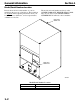
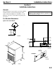
Section 2 Installation Instructions Section 2 Installation Instructions General These instructions are provided to assist the qualified installer. Check your local Yellow Pages for the name of the nearest Manitowoc distributor, or call Manitowoc Ice, Inc. for information regarding startup services. Important Failure to follow these installation guidelines may affect warranty coverage. Ice Machine Dimensions QM-45 ICE MACHINES 6.00” 15.24 CM SV1679B 3.35” 8.6 CM 2.88” 7.3 CM 3.85” 9.8 CM 22.34” 56.
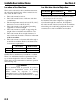
Installation Instructions Section 2 Location of Ice Machine Ice Machine Heat of Rejection The location selected for the ice machine must meet the following criteria. If any of these criteria are not met, select another location. Series Heat of Rejection* Ice Machine Air Conditioning** Peak QM-45 1750 2600 * B.T.U./Hour ** Because the heat of rejection varies during the ice making cycle, the figure shown is an average. • • • • • • • The location must be indoors.
Section 2 Installation Instructions Leveling the Ice Machine 1. Screw the leveling legs onto the bottom of the ice machine. 2. Screw the foot of each leg in as far as possible. Important Level the ice machine from front to back and side to side CAUTION The legs must be screwed in tightly to prevent them from bending. 3. Move the ice machine into its final position. 4. Level the ice machine to assure that the siphon system functions correctly. Use a level on top of the ice machine.
Installation Instructions THIS PAGE INTENTIONALLY LEFT BLANK 2-4 Section 2
Section 2 Installation Instructions Electrical Service GENERAL WARNING All wiring must conform to local, state and national codes. VOLTAGE The maximum allowable voltage variation is ± 10% of the rated voltage on the ice machine model/serial number nameplate at start-up (when the electrical load is highest). WARNING The ice machine must be grounded in accordance with national and local electrical codes. FUSE/CIRCUIT BREAKER A separate fuse/circuit breaker must be provided for each ice machine.
Installation Instructions Section 2 Water Service/Drains WATER SUPPLY Local water conditions may require treatment of the water to inhibit scale formation, filter sediment, remove chlorine, and improve taste and clarity. Important If you are installing a Manitowoc Tri-Liminator water filter system, refer to the Installation Instructions supplied with the filter system for ice making water inlet connections.
Section 2 Installation Instructions WATER SUPPLY AND DRAIN LINE SIZING/CONNECTIONS CAUTION Plumbing must conform to state and local codes. Location Water Temperature Water Pressure Ice Machine Fitting Ice Making Water Inlet 33°F (0.6°C) Min. 90°F (32.2°C) Max. 20 psi (137.9 kPA) Min. 80 psi (551.5 kPA) Max. 3/8” Female Pipe Thread Bin Drain --- --- Tubing Size Up to Ice Machine Fitting 3/8” (9.5 mm) minimum inside diameter 3/4” (19.
Installation Instructions Installation Checklist Is the ice machine level? Has all of the internal packing been removed? Have all of the electrical and water connections been made? Has the supply voltage been tested and checked against the rating on the nameplate? Is there proper clearance around the ice machine for air circulation? Has the ice machine been installed where ambient temperatures will remain in the range of 35° - 110°F (1.7° - 43.
Section 3 Ice Machine Operation Ice Machine Operation Component Identification ICE THICKNESS PROBE FLOAT VALVE ASSEMBLY WATER DISTRIBUTION TUBE SIPHON CAP EVAPORATOR BIN SWITCH MAGNET SV1731A ICE DAMPER WATER PUMP WATER TROUGH CONDENSER AIR FILTER ON/OFF/WASH TOGGLE SWITCH SV1733 COMPRESSOR COMPARTMENT ACCESS SCREWS 3-1
Ice Machine Operation Section 3 Ice Making Sequence of Operation INITIAL START-UP OR START-UP AFTER AUTOMATIC SHUT-OFF 1. Pressure Equalization Before the compressor starts the hot gas valve is energized for 15 seconds to equalize pressures during the initial refrigeration system start-up. 2. Refrigeration System Start-Up The compressor starts after the 15-second pressure equalization, and remains on throughout the entire Freeze and Harvest Sequences.
Section 3 Ice Machine Operation QM45 SELF-CONTAINED AIR COOLED MODELS ICE MAKING SEQUENCE OF OPERATION CONTROL BOARD RELAYS RELAY 1 2 3 WATER PUMP HOT GAS VALVE RELAY COIL OFF ON OFF OFF OFF 15 Seconds OFF ON ON ON ON 5 Seconds OFF OFF ON ON ON 30 Seconds INITIAL START-UP/or START UP AFTER AUTO SHUTOFF: 1. Pressure Equalization 2. Refrigeration System Start-up 3A 3B * LENGTH of “ON” TIME COMPRESSOR CONDENSER FAN MOTOR FREEZE SEQUENCE: 3. Pre-Chill 4.
Ice Machine Operation Section 3 Operational Checks GENERAL Your Manitowoc ice machine was factory-operated and adjusted before shipment. Normally, a newly installed ice machine does not require any adjustment.
Section 3 Ice Machine Operation ICE THICKNESS CHECK The ice thickness probe is factory-set to maintain the ice bridge thickness at 1/8” (3.2 mm). 1. Inspect the bridge connecting the cubes. It should be about 1/8” (3.2 mm) thick. 2. If adjustment is necessary, turn the ice thickness probe adjustment screw clockwise to increase bridge thickness, or counterclockwise to decrease bridge thickness. NOTE: Turning the adjustment 1/3 of a turn will change the ice thickness about 1/16” (1.5 mm).
Ice Machine Operation THIS PAGE INTENTIONALLY LEFT BLANK 3-6 Section 3
Section 4 Maintenance Section 4 Maintenance Interior Cleaning and Sanitizing GENERAL Clean and sanitize the ice machine every six months for efficient operation. If the ice machine requires more frequent cleaning and sanitizing, consult a qualified service company to test the water quality and recommend appropriate water treatment. The ice machine must be taken apart for cleaning and sanitizing. CLEANING AND SANITIZING PROCEDURE CAUTION Do not mix Ice Machine Cleaner and Sanitizer solutions together.
Maintenance Section 4 C. Remove the Ice Thickness Probe WARNING Disconnect electric power to the ice machine at the electric switch box before proceeding. • Compress the side of the ice thickness probe near the top hinge pin and remove it from the bracket. ICE THICKNESS PROBE Step 6: Remove parts for cleaning. A. Remove the Vinyl Hose • Disconnect the water hose from the distribution tube and water pump. B.
Section 4 Maintenance E. Remove the Float Valve D. Remove the Water Distribution Tube 3 1. LIFT UP 2. SLIDE BACK 3. SLIDE TO RIGHT • 2 1 Turn the splash shield counterclockwise one or two turns. THUMBSCREW DISTRIBUTION TUBE FLOAT VALVE BRACKET COMPRESSION FITTING SHUT-OFF VALVE LOCATING PIN CAP AND FILTER SCREEN SV127 THUMBSCREW SPLASH SHIELD Water Distribution Tube Removal • • Loosen the two thumbscrews, which secure the distribution tube.
Maintenance Section 4 F. Remove the Water Trough G. Remove the Ice Damper • • • • • Apply downward pressure on the siphon tube and remove from the bottom of the water trough. Remove the upper thumbscrew. While supporting the water trough remove the two thumbscrews from beneath the water trough. Remove the water trough from the bin area • • Grasp ice damper and apply pressure toward the left hand mounting bracket. Apply pressure to the right hand mounting bracket with thumb.
Section 4 Maintenance H. Remove the Bin Door • Grasp the rear of the bin door and pull bin door forward approximately 5”. • Slide bin door to the rear while applying upward pressure (The rear door pins will ride up into the track slot and slide backward to the stop tab). • While applying pressure against the bin door pull down on the rear of each bin door track until the door pins clear the stop tabs. • Slide the rear door pins off the end and then below the door track.
Maintenance Section 4 Step 12 Use 1/2 of the sanitizer/water solution to sanitize all foodzone surfaces of the ice machine and bin. Use a cloth or sponge to liberally apply the solution. When sanitizing, pay particular attention to the following areas: • Evaporator plastic parts - including top, bottom and sides • Bin bottom, sides and top Do not rinse the sanitized areas. Step 13 Replace all removed components.
Section 4 Maintenance ICE MACHINE INSPECTION Check all water fittings and lines for leaks. Also, make sure the refrigeration tubing is not rubbing or vibrating against other tubing, panels, etc. Do not put anything (boxes, etc.) in front of the ice machine. There must be adequate airflow through and around the ice machine to maximize ice production and ensure long component life. EXTERIOR CLEANING Clean the area around the ice machine as often as necessary to maintain cleanliness and efficient operation.
Maintenance REMOVAL FROM SERVICE WINTERIZATION Special precautions must be taken if the ice machine is to be removed from service for an extended period of time or exposed to ambient temperatures of 32°F (0°C) or below. CAUTION If water is allowed to remain in the ice machine in freezing temperatures, severe damage to some components could result. Damage of this nature is not covered by the warranty. Follow the applicable procedure below. SELF-CONTAINED AIR-COOLED ICE MACHINES 1.
Section 5 Before Calling for Service Section 5 Before Calling for Service Checklist If a problem arises during operation of your ice machine, follow the checklist below before calling for service. Routine adjustments and maintenance procedures are not covered by the warranty. Problem Possible Cause Ice machine does not operate. No electrical power to the ice machine. ON/OFF/ WASH toggle switch set improperly. Damper in open position (down).
Before Calling for Service Section 5 Problem Possible Cause Ice machine produces shallow Ice thickness probe is out of or incomplete cubes, or the ice adjustment. fill pattern on the evaporator is Water trough level is to high or too low. incomplete. Water float valve filter screen is dirty. Water filtration is poor. Hot incoming water. Water float valve is not working. Incorrect incoming water pressure. Ice machine is not level. Low ice capacity. Water float valve filter screen is dirty.
Section 5 SAFETY LIMITS General In addition to standard safety controls, the control board has two built in safety limit controls which protect the ice machine from major component failures. Safety Limit #1: If the freeze time reaches 60 minutes, the control board automatically initiates a harvest cycle. If three consecutive 60-minute freeze cycles occur, the ice machine stops. Safety Limit #2: If the harvest time reaches 3.
Before Calling for Service Section 5 Safety Limit #1 Freeze time exceeds 60 minutes for 3 consecutive freeze cycles. Possible Cause Improper installation Water system • • • • • • • • • • • • • • • • • • • • • • • • • Electrical system Restricted condenser air flow (air-cooled models) Refrigeration system Check/Correct See “Installation Instructions” Section two of this manual Low water pressure (20 psi minimum.) High water pressure (80 psi maximum.) High water temperature (90°F/32.2°C maximum.
MANITOWOC ICE, INC. Web Site - www.manitowocice.com ©2006 Manitowoc Ice, Inc.