LEAK CHECKING CONDENSER AND WATER REGULATING VALVE REMOVAL FROM INTERNATIONALIZATION 40 EVACUATION AND RECHARGING 41 SEVERE SYSTEM CONTAMINATION General Determining Severity of Contamination and Clean-Up Procedures Mild System Contamination Clean-Up Procedures Severe System Contamination Clean-Up Procedures MANITOBA ICE, INC. 2110 South 26th Street P.O. Box 1720 Manitoba, Wi 54221-1720 Phone: (920} 682-0161 Fax: (920) 683-7585 Web Site: www.manitowocice.
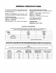
GENERAL SPECIFICATIONS This section is not intended to be a guideline to install the ice machine.
WARRANTY INFORMATION IMPORTANT Read this section very carefully for warranty explanation. {Refer to Warranty Bond for complete details.} OWNER WARRANTY REGISTRATION CARD Warranty coverage begins the day the ice machine is installed. IMPORTANT To validate the installation date, the OWNER WARRANTY REGISTRATION CARD must be mailed in. {1 the card was not returned, Manitoba will use the date of sale to the Manitoba Distributor as the first day of warranty coverage for your new ice machine.
Please contact your local Manitoba Distributor or Manitoba Ice, Inc. for further information regarding ; warranty coverage. (NOTE: Have model and serial numbers of ice machine available when calling. See Figure 1 for location of model and serial numbers.} Note: The $/N decal may be on right side. Y1013 FIGURE 1.
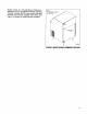
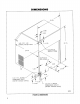
DIMENSIONS 3/8 FP.T.ICE MAKING WATER INLET 3/4 FPT BIN DRAIN ELECTRICAL SUPPLY CORD 1/2 F.R.T. WATER CONDENSER INLET (WATER CODED UNITS) 1/2 FPS. WATER CONDENSER OUTLET (WATER COOLED UNITS) sviie2 FIGURE 2.
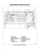
COMPONENT IDENTIFICATION 1. OVERFLOW TUBE 9. SUMP TROUGH 2. DISTRIBUTION TUBE 10, THUMB SCREW 3. DISTRIBUTION TUBE SEAL 11, TUBING 1/4" OVERFLOW 4. DISTRIBUTION TUBE SPRING CLIP 12, TYSON TUBING, 1/2" 1D X 3/4" QD 5. END PLUG 13. WATER CURTAIN (NOT SHOWN) 6. EVAPORATOR ‘14, CURTAIN BRACKET 7. FLOAT VALVE 15. WATER PUMP 8. ICE THICKNESS CONTROL 16. FLUSH CAP SV1163 FIGURE 4.
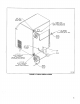
. AIR CONDENSER . COMPRESSOR FAN . FAN CYCLING CONTROL . HOT GAS SOLENOID DRIER shoehorn V1168 FIGURE 6.
INTERIOR CLEANING For efficient operation, clean and sanitize ice machine every six months. IMPORTANT Do not use hot water. If ice machine requires cleaning and sanitizing more frequently, consult a qualified service company fo test the water quality and recommend appropriate water treatment. REMOVAL OF PARTS FOR CLEANING 1. Loosen two screws holding top caver in place and remove. 2.
REMOVE FLOAT VALVE (Figure 9) 1. Turn valve splash shield clockwise a full turn or two, then pull the naive off the mounting bracket. 2. Disconnect the water inlet tube from the float valve at the compression fitting. 3. Unscrew filter screen and cap. SHUT OFF VALVE STRAINER\ B SPLASH SHIELD FLOAT VALUE WATER LEVEL WATER TROUGH Y1189 FIGURE 9. FLOAT VALVE REMOVAL REMOVE DISTRIBUTION TUBE {Figure 10} 1. Remove distribution tube from the two spring clips holding it in place.
NOTE Position the holes in the inner and outer tubes 180° opposite each other when reassembling. The end of the inner distribution tube without holes must extend from the outer tube when reassembled to allow for attachment of the water ling from the pump. REMOVE ICE THICKNESS PROBE {Figure SORES A warning Disconnect electric power to ice machine before proceeding. 1. Disconnect wire leads from inside electrical control! box. 2. Compress side of probe at top near hinge pin and disengage it from the bracket.
2. Use the cleaning solution and a brush or sponge to remove scale bulls-up from the top, sides and bottom extrusions, the inside of the ice machine panels, and the entire inside of the ice bin. A dirty top extrusion, Figure 10, could result in uneven water flow over the evaporator. Ensure all scale and dirt are removed. 3. Thoroughly rinse with clean water all parts and surfaces washed with the cleaning solution.
SANITIZING Sanitizer is used for removal of algae or slime AND AFTER USE OF MANITOBA ICE MACHINE CLEANER. It Is not used for removal of lime scale or other mineral deposits. 1. Loosen two screws holding top cover in place and remove top cover. 2. SetiCE/OFF/WATER PUMP switch at OFF after ice falls from evaporator at completion of harvest cycle or set switch at OFF and allow ice to melt off evaporator. A caution Never use any type of object to force ice from evaporator as damage may result. 3.
SEQUENCE OF OPERATION FREEZE CYCLE The water flows over the evaporator, forming ice on Place main toggle switching ICE position, This energizes ~ @evaporator. The frieze cycle will last approximately the compressor, fan motor (air cooled models) and 10-30 minutes, depending on air and water conditions. water pump. (Refer to Cycle Time Chart, page 33.
[Fl men pressure valor [[lion pressure o FREEZE CYCLE EVAPORATOR CAPTURE T (SSTSSITIITNIITTTNG, e TRy {oaxsReesesy N N year EXCHANGE Ly ACCUMULATOR TARE X HOT GAS SOLENOID VALUE CONDENSER ) more $v1188 W PRESSURE LOUD [RN LOW PRESSURE VAPOR FIGURE 15, FREEZE CYCLE REFRIGERATION SEQUENCE Freeze Cycle Refrigeration Sequence The refrigerant is absorbing heat from the water running over the evaporator surface. The suction pressure gradually drops as ice forms.
HARVEST CYCLE The harvest cycle begins when water flowing over the ice on the evaporator contacts the probes on the ice thickness control, After a constant 6-10 seconds of wale contact, the relay in the unitized sensor board is energized, changing contacts #5 and #6. As hot gas warms the evaporator, the ice cubes slide, as a unit, off the evaporator into the storage bin. The harvest cycle will last approximately 1 to 2 minutes.
HARVEST CYCLE CAPTURE HOT GAS SOLENOID VALVE [iron pressure baron [Front pressure noun Now pressure Laue follow PRESSURE vapor itself FIGURE 18. HARVEST CYCLE REFRIGERATION SEQUENCE Harvest Cycle Refrigeration Sequence Hot gas flows through the energized hot gas valve heating the evaporator. The hot gas valve is sized to allow the proper amount of refrigerant into the evaporator. This specific sizing assures proper heat transfer without the refrigerant condensing and slugging the compressor.
AUTOMATIC SHUT-OFF seconds, the contact on the 7-second delay relay {Full Bin of Ice) opens, DE-energizing the compressor and fan moor. The open bin switch disconnects power io the other When ice storage bin becomes full, the last harvesting components. The return of the water curtain closes the ice cubes do not completely clear the water curtain. bin switch and the ice machine starts a new freeze cycle.
SERVICE DIAGNOSTIC CHART Symptom Possible Cause Corrective Action ice machine will not run, INTEROFFICE PUMP switch: a. No tin ICE position. b. Defective/miswired. High pressure cut-out control tripped: a. Condenser water pressure fow or off {water cooled). b. Condenser water temperature above 80°F (water cooled). c. Dirty condenser. d. Refrigerant overcharge. e. High side refrigerant lines or component plugged. f. H.P.C.Q. control defective. Circuit breaker tripped or blown fuse. Bin switch: a.
Symptom Possible Cause Corrective Action Ice cubes too large/small. Ice thickness probe out of adjustment. Adjust ice thickness probe, page 24. Shallow or incomplete cubes; incomplete ice fill pattern on evaporator. ice thickness probe out of adjustment. fce machine dirty. Water filtration, ice making water inlet supply too warm.. Incorrect incoming water pressure, Refrigeration problem. Adjust ice thickness probe, page 24. Clean and sanitize ice machine, refer to pages 10 and 14. Replace filters.
COMPONENT FUNCTION, SPECIFICATIONS AND CHECK PROCEDURES BIN SWITCH Function Bin switch operation is controlled by movement of the water curtain (refer to Water Curtain, page 25). it resets ice machine to freeze cycle by momentarily interrupting power to the unitized ice sensor board as ice falls from the evaporator, The bin switch also shuts the ice machine off when the bin is full. Specifications Single pole/single throw, normally closed. NOTE The N.O. terminal is not used. Check Procedure 1.
Specifications Gut-out ~ 175 psi {5 psi) Cut-in — 225 psi (5 psi) Check Procedure 1. Verify fan motor winding are not open or grounded and fan spins freely. 2. Hook voltmeter in parable! (across) to the fan cycle control, leaving wires attached. 3. Pressure below 175 psi — read line voltage and fan should be off, Replace Fan Cycle Control if: Control does not operate within psi range listed above. FLOAT VALVE Function Maintains correct water level in water trough. Check Procedure 1.
ICE THICKNESS PROBE Function Maintain correct ice thickness. Check Procedure Verify that wire connections are clean and tight. Inspect bridge connecting the cubes. The ice thickness probe is factory set to maintain ice thickness. If adjustment is necessary, proceed as follows: 1. Turn adjustment screw {Figure 23} on ice thickness probe clockwise to increase thickness, counterclockwise to decrease thickness.
WATER CURTAIN Function 1. Prevent water from splashing into bin. 2. Acts as a lever to depress and release bin switch activating pin {refer to Bin Switch, page 22) as ice falls from the evaporator. Check Procedure 1. Pull bottom of water curtain (Figure 25) away from evaporator, then release, Curtain should flat back to evaporator. AND ADJUST HANGERS TO ELIMINATE SIDE TO SIDE MOVEMENT CURTAIN HANGER (Lift tabs with Wombs while lifting hanger) CURTAIN CURTAIN PIN B65Vodd FIGURE 25. WATER CURTAIN CHECK 2.
7-SECOND OFF DELAY RELAY Function 1. Prevents interruption of compressor operation when going from the harvest cycle o the freeze cycle. 2. DE-energizes the compressor and fan motor {(air cooled only) when bin is full or when turned off at toggle switch, Specifications 85-230 volt, 50/60 Hertz. Check Procedure Clip voltmeter leads across the normally open relay contacts L1 and 7. Keep all wire glads attached. NORMAL OPERATIONAL SEQUENCE sVii74 FIGURE 26.
DIAGNOSING ELECTRONIC CONTROL CIRCUITRY UNITIZED SENSOR BOARD The ice machine uses a unitized sensor board with a plug-in ice thickness probe to control the ice thickness by initiating the harvest cycle. Function 1. A relay energizes or DE-energizes the electrical components during the harvest cycle. 2. Electronics sense when the water is in contact with the ice thickness control probe.
Step 3: Disconnect ice thickness control probe wires from bulkhead {upper brightener. Connect the jumper wire to the bulkhead terminals. Does the ice machine go into the harvester? [F NO: Proceed to Step 4. [F YES: The ice thickness probe is the cause of malfunction. All other components are operating properly. The ice thickness probe may be dirty. Attempt to clean before replacing. Step 4: Disconnect wires from terminals 20 and 21 on board.
DIAGNOSING COMPRESSOR AND START COMPONENTS ELECTRICALLY TO L1 o START CAPACITOR POWER e SUPPLY W 19 COMPRESSOR % 5 ¢ COMPRESSOR TERMINALS SANFORD LOCKED oL VOLTAGES ~ COMPRESSOR OHM VALUES® ROTOR CHANGE AMPS (DISUNION 3aS) cs [ As 115/601 SC108 (600 ML) 208/230/6011 SC-108 174 78 252 27 22.0Z. (600 ML) 2201240/5011 Scala 134 5.1 182 158 2207, (600 ML) ‘Compressor coatroom temperature BY1175 FIGURE 29.
e. Check winding resistance against values given in charm, The resistance values from C-R and C-8 added together should equal the reading storeroom. 5. Capacitor check (run and start): 30 Capacitors may show visual evidence of failure, such as a bulged terminal end or a ruptured membrane. However, do nof assume a capacitor fs good just because there are no visual signs of failure. An effective test is to disconnect leads to the capacitor in the ice machine and connect them to a good capacitor. c.
REFRIGERATION AND OTHER NON-ELECTRICAL PROBLEMS INTRODUCTION Refrigeration components will react and try to compensate for non refrigeration component problems. By following a step-by-step procedure problems that affect the refrigeration sequence can be identified without needless changing of refrigeration components. You must make a visual inspection and analyze water problems before diagnosing refrigeration problems. VISUAL INSPECTION Talk to the ice machine user to identify the perceived problem(s).
WATER SYSTEM Water related problems iry ice machines often have the ample is water leaking out of sump trough during the same symptoms as a refrigeration system malfunction. freeze cycle and a restricted capillary tube. The character area failures must be identified and eliminated prior to changing of refrigeration components. An characteristics of both failures are similar. CHECK WATER RELATED PROBLEMS Possible Problem Actual Finding Corrective Measure 1. Water area (evaporator) dirty. Clean. 2.
ICE PRODUCTION Air-Cooled The amount of ice a machine produces is in direct Condenser Freeze Time relationship to water and air temperatures, this means Ambient Water Temp. an ice machine produces more ice in & 70°F room with Temp Harvest 50°F water than in a 90°F room with 70° F water. o 50°F 70°F 90°F Time ICE PRODUCTION CHARTS gg 3'5 190"134 j;}g Lbs. (Los. ot loe per 24 Hours) 90 945 | 1016 | 1419 | 12 100 10-18 1117 18-24 Water-Cooled Use the following to check and compare to proper ice Water Temp.
ICE FILL PATTERN The ice fill pattern on an evaporator helps to indicate if the proper flow of refrigerant is entering the evaporator. The copper tubing routing on the back of the evaporator must be considered when analyzing the ice fill pattern. g DT SV1150 FIGURE 30. EVAPORATOR COPPER TUBING ROUTING Compare the following ice fill patterns to the infer and outlet of the evaporator to "ses” what refrigerant is doing in the evaporator.
OPERATIONAL PRESSURE CHARTS Air-Cooled Water-Cooled Frieze Cycle Harvest Cycles Freeze Cycle Harvest Cycle Ambient End Suction Head Suction Ambient Head Suction Head Suction Temp, Pressure | Pressure | Pressure | Pressure Pressure | Pressure | Pressure | Pressure °F PSI PSI PSI PSI F PIG PSI PSI SIGN 50 175225 | 35-18 125175 | 65100 50 220-230 3526 160-200 | 85100 70 180250 | 35-18 125175 | 65-100 70 200-250 | 3525 180200 | 90108 80 215270 | 3518 185485 | 75110 80 220233 | 3525 160-200 | 90-106 90 290290 |
DISCHARGE PRESSURE LOW Eliminate the possible problems in the order listed on chart and follow appropriate corrective measures. Passable Problem Actual Finding Corrective Measure 1. Load conditions low (air water temperatures}. 2. Water regulating naive (water cooled condenser): about of adjustment. b. Leaking water during harvest cycle, ¢. Detective. 3. Fan motor/fan cycling switch defective. 4. Low refrigerant charge. 5. Partially plugged capillary tube.
SUCTION PRESSURE HIGH Eliminate the possible problems in the order listed on chart and follow appropriate corrective measure. Possible Problem Actual Finding Corrective Measure 1. High discharge pressure affecting low side, 2. Hot gas valve stuck wide open. 3. Inefficient compressor (do not perform pump down test). See Discharge Pressure High, page 35. Replace valve, page 38. Replace compressor as necessary.
HOT GAS VALVE CHECK INEFFICIENT COMPRESSOR SYMPTOMS POSSIBLE PROBLEMS: 1. Suction valves (inefficient compressor). 1. Improper valve, A hot gas valve requires a specific orifice size which meters the proper amount of hot gas flow into the evaporator during the harvest cycle. Replace defective hot gas valves with original Townswoman replacement parts only. Refer to your Pars Manual for proper valve application. 2.
LEAK CHECKING CONDENSER AND WATER REGULATING VALVE IMPORTANT Both the condenser and water regulating valve must be leak checked. o coarsen Gt RN Comer LEAK CHECKING WATER REGULATING VALVE NOTE Water regulating valve must be disconnected from the condenser. Completely dry water valve inlet and outlet to eliminate false readings from the leak defector, 8y1178 FIGURE 33. CONDENSER LEAK CHECK POINTS LEAK CHECKING CONDENSER 3. 4. 5, Set WATERPROOFING PUMP switch at OFF. Turn off incoming condenser water supply.
REMOVAL FROM INTERNATIONALIZATION ‘You must take special precautions if the ice machine is to be removed from service for extended periods or exposed to ambient temperatures of 32°F or below. A CAUTION IF WATER IS ALLOWED TO REMAIN IN THE MACHINE IN FREEZING AMBIENT TEMPERATURES, IT WILL FREEZE, RESULTING IN SEVERE DAMAGE TO COMPONENTS. A FAILURE OF THIS NATURE IS NOT COVERED BY WARRANTY. Air-Cooled Machines 1. Disconnect electric power at circuit breaker or electric service switch. 2.
EVACUATION AND RECHARGING REMOVAL OF REFRIGERANT Do not purge the refrigerant to the atmosphere. Recapture refrigerant using recovery equipment by following specific manufacturer's recommendations. IMPORTANT Manitoba Ice, Inc. assumes no responsibility for use of recycled refrigerant. Damage resulting from the use of contaminated recycled refrigerant is the sale responsibility of the servicing company.
CLOSED OPEN T0 TO LOW SIDE HIGH SIDE CLOSED PEN GBSVOsS Open high side manifold gauge valve. Open charging cylinder and add measured nameplate charge into high side. Allow system fo “settee” for 2 or 3 minutes after charging. Close high side on manifold gauge set. Place toggle switch in ICE position and add remaining vapor charge through suction service valve (if necessary), Ensure all vapor in charging hoses is drawn into the ice machine before disconnecting manifold gauges.
MANITOBA ICE, INC. 2110 South 26th Street P.O. Box 1720 Manitoba, Wl 54221-1720 Thane: (920) 682-0161 Fax: (920) 683-7585 Web Site: www manitowocice.com © 1999 Manitoba Ice, Inc Li tho in U.S.
SEVERE SYSTEM CONTAMINATION GENERAL It is important to read and understand the following text regarding severe system contaminator. The purpose is to describe the basic requirements for restoring contaminated systems to reliable service. IMPORTANT Manitoba Ice, Inc. assumes no responsibility for use of recycled refrigerant. Damage resulting from the use of contaminated recycled refrigerant is the sole responsibility of the servicing company.
MILD SYSTEM CONTAMINATION CLEAN-UP PROCEDURES 1. Replace failed components i applicable. If compressor checks god, change oil in compressor. 2. Replace liquid line drier. 3. Follow normal evacuation procedure, page 39, except replace the evacuation step with the following: NOTE if contamination is from moisture, the use of heat lamps or heaters is recommended during evacuation. Place heat lamps at the compressor, condenser, and at the evaporator prior to evacuation.