Flake / Chiplet Model Ice Machines Flake Models QF0400/QF0800/ QF2200/QF2300 Chiplet Models QC0700 Service Manual Revised 8/2003 Part Number 80-1214-3 07/03
Safety Notices Procedural Notices As you work on a Flake / Chiplet Series Ice Machine, be sure to pay close attention to the safety notices in this manual. Disregarding the notices may lead to serious injury and/or damage to the ice machine. As you work on a Flake / Chiplet Series Ice Machine, be sure to read the procedural notices in this manual. These notices supply helpful information which may assist you as you work.
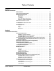
Table of Contents Section 1 General Information Model Numbers . . . . . . . . . . . . . . . . . . . . . . . . . . . . . . . . . . . . . . . . . . . . . . . . . . How to Read a Model Number . . . . . . . . . . . . . . . . . . . . . . . . . . . . . . . . . . . . . . Remote Condensing Unit . . . . . . . . . . . . . . . . . . . . . . . . . . . . . . . . . . . . . . . . . . Accessories . . . . . . . . . . . . . . . . . . . . . . . . . . . . . . . . . . . . . . . . . . . . . . . . . . Bin Caster . . . . . . . .
Table of Contents (continued) Ice Machine Head Section Water Supply and Drains . . . . . . . . . . . . . . . . . . . Potable Water Supply . . . . . . . . . . . . . . . . . . . . . . . . . . . . . . . . . . . . . . . . . . Potable Water Inlet Lines . . . . . . . . . . . . . . . . . . . . . . . . . . . . . . . . . . . . . . . Drain Connections . . . . . . . . . . . . . . . . . . . . . . . . . . . . . . . . . . . . . . . . . . . . Cooling Tower Applications (Water-Cooled Models) . . . . . . . . . . . . . . . .
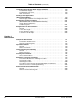
Table of Contents (continued) Section 4 Ice Machine Sequence of Operation QF400/QC700/QF800 . . . . . . . . . . . . . . . . . . . . . . . . . . . . . . . . . . . . . . . . . . . . . . Prior to Start-Up . . . . . . . . . . . . . . . . . . . . . . . . . . . . . . . . . . . . . . . . . . . . . . . Initial Start-Up . . . . . . . . . . . . . . . . . . . . . . . . . . . . . . . . . . . . . . . . . . . . . . . . Automatic Shut-Off . . . . . . . . . . . . . . . . . . . . . . . . . . . . . . . . . . . . . . . . . .
Table of Contents (continued) Control Board . . . . . . . . . . . . . . . . . . . . . . . . . . . . . . . . . . . . . . . . . . . . . . . . . . . Component Specifications and Diagnostics . . . . . . . . . . . . . . . . . . . . . . . . . . ICE/OFF/CLEAN Toggle Switch . . . . . . . . . . . . . . . . . . . . . . . . . . . . . . . . . . Bin Level Probe . . . . . . . . . . . . . . . . . . . . . . . . . . . . . . . . . . . . . . . . . . . . . . Motor Speed Sensor . . . . . . . . . . . . . . . . . . . . . . . . .
Table of Contents (continued) Refrigerant Recovery/Evacuation and Recharging . . . . . . . . . . . . . . . . . . . . . . Refrigerant Recovery/Evacuation . . . . . . . . . . . . . . . . . . . . . . . . . . . . . . . . . System Contamination Clean-Up . . . . . . . . . . . . . . . . . . . . . . . . . . . . . . . . . . Replacing Pressure Controls Without Removing Refrigerant Charge . . . . . . . . . . . . . . . . . . . . . . . . . . . . . . . . . . . . Filter-Driers . . . . . . . . . . . . . . . . . . . . . . .
Table of Contents (continued) 6 Revised 8/2003 Part No.
Section 1 General Information Model Numbers Accessories This manual covers the following models: BIN CASTER Flake Ice Undercounter Self-Contained Air-Cooled Self-Contained Air-Cooled Self-Contained Water Cooled Remote Air-Cooled Chiplet Ice Condensing Unit QF0406A NA NA QF0806A QC0708A NA QF0807W QC0709W NA QF2296N QF2396N NA NA RFC2085 RFC2385 Replaces standard legs. ICE BAGGER Maximize profits from bagged ice sales with this convenient accessory.
General Information Section 1 Model/Serial Number Location These numbers are required when requesting information from your local Manitowoc distributor, service representative, or Manitowoc Ice, Inc. SV2019 The model and serial number are listed on the OWNER WARRANTY REGISTRATION CARD. They are also listed on the MODEL/SERIAL NUMBER DECAL affixed to the ice machine head section and condensing unit. Both model/serial numbers must be referenced to obtain warranty or service information.
Section 1 General Information Owner Warranty Registration Card EXCLUSIONS GENERAL The following items are not included in the ice machine’s warranty coverage: Warranty coverage begins the day the ice machine is installed. Important Complete and mail the OWNER WARRANTY REGISTRATION CARD as soon as possible to validate the installation date.
General Information Section 1 THIS PAGE INTENTIONALLY LEFT BLANK 1-4 Revised 8/2003 Part No.
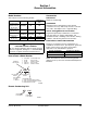
Section 2 Installation Instructions Ice Machine Dimensions QF400 AIR COOLED ICE MACHINE QC700/QF800 AIR COOLED ICE MACHINE 19” (48.2 CM) 26” (66 CM) 7.2” (18.2 CM) 3.04” (7.72 CM) 22” (55.88 CM) 24.5” (62.23 CM) 32.5” (82.55 CM) 26.5” (67.3 CM) 3.03” (7.7 CM) 1.36” (3.5 CM) 6” (15.24 CM) 26.5” (67.3 CM) SV2050 5.9” (15 CM) 1.6” (4 CM) 2.9” (7.3 CM) SV2003 3” (7.6 CM) Important Failure to follow these installation guidelines may affect warranty coverage.
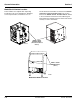
Installation Instructions Section 2 Ice Machine Head Section and Remote Condensing Unit Dimensions QF2200/QF2300 AND RFC2085/RFC2385 REMOTE CONDENSING UNIT 24.5” (62.23 CM) 30” (76.2 CM) 24.13” (53.7 CM) 34” (86.4 CM) 2.25” (5.72 CM) 4.5” (11.43 CM) 25.75” 23.5” (67.3 CM) 14.5” (36.8 CM) 14.5” (36.8 CM) 2.8” (7.12 CM) SV1784 1.8” (4.6 CM) 10.75” (27.3 CM) 9.8” (24.89 CM) 2-2 9.5” (24.1 CM) Revised 8/2003 SV1758 Part No.
Section 2 Installation Instructions Ice Machine Heat of Rejection Location of Ice Machine The location selected for the ice machine must meet the following criteria. If any of these criteria are not met, select another location. • The location must be free of airborne and other contaminants. • The air temperature must be at least 45°F (7°C), but must not exceed 110°F (43.4°C). • The water temperature must be at least 45°F (7°C), but must not exceed 90°F (32.2°C).
Installation Instructions Section 2 Leveling the Ice Storage Bin Condenser Air Baffle 1. Screw the leveling legs onto the bottom of the bin. (QC700/QF800 Air-Cooled Ice Machines Only) 2. Screw the foot of each leg in as far as possible. The air-cooled baffle prevents condenser air from recirculating. To install: ! Caution The legs must be screwed in tightly to prevent them from bending. 1. Remove the back panel screws next to the condenser. 2.
Section 2 Installation Instructions Electrical Service FUSE/CIRCUIT BREAKER GENERAL A separate fuse/circuit breaker must be provided for each ice machine. Circuit breakers must be H.A.C.R. rated (does not apply in Canada). ! Warning All wiring must conform to local, state and national codes. VOLTAGE The maximum allowable voltage variation is ±10% of the rated voltage on the ice machine model/serial number plate at start-up (when the electrical load is highest).
Installation Instructions Section 2 Electrical Requirements Ice Machine Head Section Air-Cooled Ice Machine QF400 QC700 QF800 QF2200 QF2300 Voltage Phase Cycle 115/1/60 230/1/50 115/1/60 230/1/50 230/1/60 115/1/60 230/1/50 230/1/60 115/1/60 230/1/50 230/1/60 115/1/60 230/1/50 230/1/60 Maximum Fuse/Circuit Breaker Minimum Circuit Amps Total Circuit Amps 15 15 30 20 15 30 20 15 NA NA NA NA NA NA NA NA 18.9 8.8 8.7 18.9 8.8 8.7 NA NA NA NA NA NA 9.8 4.
Section 2 Installation Instructions Ice Machine Head Section Electrical Wiring Connections QF2200 ICE MACHINE HEAD SECTION ! Warning These diagrams are not intended to show proper wire routing, wire sizing, disconnects, etc., only the correct wire connections. 115/60/1 ICE MACHINE CONNECTIONS All electrical work, including wire routing and grounding, must conform to local, state and national electrical codes.
Installation Instructions Section 2 Remote Electrical Wiring Connections RFC2385 REMOTE CONDENSING UNIT 208-230/1/60 ! Warning These diagrams are not intended to show proper wire routing, wire sizing, disconnects, etc., only the correct wire connections. CONDENSING UNIT CONNECTIONS All electrical work, including wire routing and grounding, must conform to local, state and national electrical codes.
Section 2 Installation Instructions Ice Machine Head Section Water Supply and Drains POTABLE WATER SUPPLY Local water conditions may require treatment of the water to inhibit scale formation, filter sediment, and remove chlorine odor and taste. DRAIN CONNECTIONS Follow these guidelines when installing drain lines to prevent drain water from flowing back into the ice machine and storage bin: • Drain lines must have a 1.5 inch drop per 5 feet of run (2.5 cm per meter), and must not create traps.
Installation Instructions Section 2 WATER SUPPLY AND DRAIN LINE SIZING/CONNECTIONS ! Caution Plumbing must conform to state and local codes. Location Water Temperature Water Pressure Ice Machine Fitting Ice Making Water Inlet 45°F (6°C) Min. 90°F (32.2°C) Max. 33°F (0.6°C) Min. 90°F (32.2°C) Max. 20 psi (137.9 kPA) Min. 80 psi (551.5 kPA) Max. 20 psi (137.9 kPA) Min. 150 psi (1034.2 kPA) Max. 3/8" Female Pipe Thread Tubing Size Up to Ice Machine Fitting 3/8" (9.
Section 2 Installation Instructions Refrigeration System Installation Factory Equipment Refrigeration Amounts (QF2200/RFC2085 AND QF2300/RFC2385 ONLY) ICE MACHINE HEAD SECTION QuietQube® Ice Machine Remote Single Circuit Condenser Line Set* QF2200 QF2300 RFC2085 RFC2385 RC-20 RC-30 RC-50 Each ice machine head section ships from the factory with a R-404A refrigerant charge appropriate for line sets up to 50’ in length (12.5 lbs.).
Installation Instructions Section 2 Refrigeration Line Set Installation GENERAL A. LINE SET LENGTH Refrigeration line set installations consist of vertical and horizontal line set distances between the ice machine and the condensing unit. The following guidelines, drawings and calculation methods must be followed to assure proper oil return and condensing unit/ice machine operation 100 feet (30.5 m) Length: The maximum measured length the line set can be.
Section 2 Installation Instructions C. SUCTION LINE OIL TRAPS ! Caution Do not form unwanted traps in refrigeration lines. Never coil excess refrigeration tubing. 0 to 20 feet (0 to 6.1 m) Rise: The ice machine head section has one oil trap built in which allows for a maximum condenser rise of 20 feet (6.1 m) without additional traps in the suction line. 21 to 35 feet (6.4 to 10.7 m) Rise: The suction line requires an additional Oil Trap (“S” type) to be installed.
Installation Instructions Section 2 Step 4 Connecting the line set. To prevent oxidation of the copper, purge line set and condensing unit with dry nitrogen while brazing. Connect The Line Set To The Ice Machine Head Section ! Warning The ice machine head section contains refrigerant charge. The ice machine head section contains three (3) refrigeration valves that must remain closed until proper installation of the line sets is completed.
Section 2 Installation Instructions Step 5 Pressure Test and Evacuate The Line Set and Remote Condensing Unit Step 6 Open The Valves Prior To Starting The Ice Machine. A. Slowly backseat (open-turn counterclockwise) the suction line shut off valve. Schrader valve core removal tools that allow for removal and installation of the valve cores without removing manifold gauge set hoses are recommended to decrease the evacuation time. Leave the line set shut off valves closed (front seated).
Installation Instructions Section 2 Verify O-ring in schrader valve caps are intact and reinstall on shut off valves to prevent refrigerant leakage. Replace shut off valve access caps and torque to the following specifications. Torque Value’s Stem 18-20 ft. lbs. Caps 12-15 ft. lbs. Schrader Core 1.5-3 in. lbs. To prevent condensation the entire suction line including the shut-off valve must be insulated. All insulation must be airtight and sealed at both ends.
Section 2 Installation Instructions Suction Shut Off Valve Insulation The pre-formed suction shut-off valve insulation is located in the plastic bag taped to the water curtain. A. Verify valve and schrader caps are tightened to specifications (see Step 6). PRE-FORMED INSULATION TIGHTEN VALVE CAPS TO SPECIFICATIONS SV3084 B. Place insulation over schrader valve cap and left side of valve. Position the tab between the mounting bracket and rear panel. PLACE TAB BETWEEN VALVE BODY AND PANEL SV3085 C.
Installation Instructions Section 2 THIS PAGE INTENTIONALLY LEFT BLANK 2-18 Revised 8/2003 Part No.
Section 3 Ice Machine Operation Component Identification ICE MACHINE HEAD SECTION QC700/QF800 QUARTER TURN THUMBSCREWS WATER LEVEL PROBE CLEANING SOLUTION FILL HOLE CONDENSER AIR FILTER DUMP VALVE WATER FLOAT VALVE COIL CONDENSER FAN MOTOR POTABLE WATER INLET ICE CHUTE ICE/OFF/CLEAN TOGGLE SWITCH WATER INLET QUICK DISCONNECT FITTING GEARMOTOR POTABLE WATER DRAIN SV2019 SV2022 QF400 WATER FLOAT VALVE COIL WATER LEVEL PROBES EVAPORATOR WATER INLET QUICK DISCONNECT ICE CHUTE CONTROL BOX DUMP V
Ice Machine Operation Section 3 QF2300 CLEANING SOLUTION FILL HOLE ICE CHUTE RETAINING CLAMP EVAPORATOR ELECTRICAL COMPARTMENT CONDENSER FAN MOTOR AIR CONDENSER ICE/OFF/ CLEAN TOGGLE SWITCH ICE CHUTE GEAT MOTOR/ GEAR BOX ASSEMBLY WATER LEVEL PROBES SUCTION FILTER FLOAT VALVE COMPRESSOR HEAD PRESSURE CONTROL VALVE ICE CHUTE ELBOW SV2100 RFC2385 Remote Condensing Unit DUMP VALVE SV2102 CLEANING SOLUTION FILL HOLE 3-2 WATER RESERVOIR Part Number 80-1214-3
Section 3 Ice Machine Operation Operational Checks GENERAL WATER LEVEL CHECK Manitowoc ice machines are factory-operated and adjusted before shipment. Normally, a newly installed ice machine does not require any adjustment. The float valve maintains the correct water level. The water level must allow the water level probes to maintain water contact throughout the freeze cycle. The water level is factory set and normally will not require adjustment. Check the water level during the freeze cycle.
Ice Machine Operation Section 3 Interior Cleaning and Sanitizing GENERAL You are responsible for maintaining the ice machine in accordance with the instructions in this manual. Maintenance procedures are not covered by the warranty. Manitowoc Ice Machines have three separate cleaning procedures. Clean and sanitize the ice machine every six months for efficient operation.
Section 3 Ice Machine Operation 3. Shine a flashlight through the condenser to check for dirt between the fins. If dirt remains: CLEANING THE CONDENSER ! Warning Disconnect electric power to the ice machine and the remote condenser at the electric service switch before cleaning the condenser. Air-Cooled Condenser (SELF-CONTAINED AND REMOTE MODELS) A. Blow compressed air through the condenser fins from the inside. Be careful not to bend the fan blades. B. Use a commercial condenser coil cleaner.
Ice Machine Operation Section 3 MANITOWOC’S CLEANING TECHNOLOGY Manitowoc Flake/Chiplet Ice Machines include technology that allows the initiation and completion of a cleaning or sanitizing cycle at the flip of a switch. This cycle will permit cleaning of all surfaces that come in contact with the water distribution system. Periodic maintenance must be performed that includes sanitizing the bin and adjacent surface areas, which are not contacted by the water distribution system.
Section 3 Ice Machine Operation PREVENTATIVE MAINTENANCE CLEANING PROCEDURE QF400 Use Ice machine cleaner part number 000000084 only. This cleaner is used to remove lime scale or other mineral deposits. It is not used to remove algae or slime. Refer to “Cleaning/Sanitizing Procedure” for removal of algae and slime. To initiate a cleaning cycle using Manitowoc’s Cleaning Technology use the following procedure. Step 1 Set the toggle switch to the OFF position.
Ice Machine Operation Section 3 CLEANING/SANITIZING PROCEDURE QC700/QF800/QF2300 Use Ice machine cleaner part number 000000084. Use Ice machine sanitizer part number 94-0565-3. Step 1 Remove front and top covers and set the toggle switch to the OFF position. Step 2 Remove all ice from the bin. Step 3 Disconnect water supply line at float valve quick disconnect by depressing stainless steel lever. Step 4 Remove the top cover from water reservoir.
Section 3 Ice Machine Operation CLEANING/SANITIZING PROCEDURE QF400 Use Ice machine cleaner part number 000000084. Use Ice machine sanitizer part number 94-0565-3. Step 1 Set the toggle switch to the OFF position and remove all ice from the bin. Step 2 Remove the 2 thumbscrews and white plastic panel. Step 17 Remove the water level probes from the top cover and with the wires attached, place the water level probes (stand upright) inside the water reservoir.
Ice Machine Operation Section 3 PROCEDURE TO CLEAN HEAVILY SCALED FLAKE/CHIPLET ICE MACHINES QF400/QC700/QF800/QF2300 Step 4 Refer to chart below: Step 5 Remove all water from the evaporator and water reservoir. Start an ice making cycle by moving the toggle switch to the ICE position. Water will flow through the water dump valve and down the drain for 45 seconds. After 45 seconds move the toggle switch to the OFF position. Remove the plug from the top cover of the water reservoir.
Section 3 Ice Machine Operation REMOVAL OF PARTS FOR CLEANING/SANITIZING ! Warning Disconnect electric power to the ice machine at the electric switch box before proceeding. ! Warning Wear rubber gloves and safety goggles (and/or face shield) when handling Ice Machine Cleaner or Sanitizer. 3. Soak the removed part(s) in a properly mixed solution of cleaner and water. Solution Type Cleaner Water 1 gal. (4 l) Mixed With 16 oz (500 ml) cleaner Part Number 000000084 4.
Ice Machine Operation Section 3 Water Level Probe Removal Water Reservoir Cover Removal QF400/QC700/QF800/QF2300 1. Place the toggle switch in the OFF position, turn off the water supply and disconnect electrical power to the ice machine. Water Level Probe Removal 1. Place the toggle switch in the OFF position, turn off the water supply and disconnect electrical power to the ice machine. 2. Remove water level probes. 2.
Section 3 Ice Machine Operation Float Valve Removal Water Reservoir Cover Removal QF2300 1. Place the toggle switch in the OFF position, turn off the water supply and disconnect electrical power to the ice machine. 2. Remove water level probes. 1. Place the toggle switch in the OFF position, turn off the water supply and disconnect electrical power to the ice machine. 2. Disconnect water supply line at float valve quick disconnect by depressing stainless steel lever. 3. Remove water float valve coil. 3.
Ice Machine Operation Section 3 Ice Diverter Removal Water Reservoir Removal 1. Place the toggle switch in the OFF position and turn off the water supply to the ice machine at the water service valve. 2. Disconnect water supply line at float valve quick disconnect by depressing stainless steel lever. 3. Place the toggle switch in the ICE position. The dump valve will open and the float reservoir will empty. 4.
Section 3 Ice Machine Operation Ice Chute Removal QF2300 QC700/QF800 1. Follow steps to remove float reservoir. 2. The ice chute and ice chute grommet will be removed as a unit. Pull forward on the top of the ice chute, and slide the ice chute and grommet off the end of the evaporator spout. 1. Place the toggle switch in the OFF position, turn off the water supply and disconnect electrical power to the ice machine. 2. Remove ice chute retaining clamp from top of evaporator. 3.
Ice Machine Operation Section 3 Bin Door Removal Cabinet Removal QF0400 QF0400 Door removal allows easier access for cleaning and sanitizing. 1. Remove all ice from bin and disconnect power. 2. Remove thumbscrews and evaporator panel. 1. Disconnect the electrical power to the ice machine and remove ice from bin. 3. Remove three screws from the bottom of the left and right side of cabinet. 2. Grasp the rear of the bin door and pull bin door forward approximately 5”. 4.
Section 3 Ice Machine Operation Water Dump Valve The water dump valve normally does not require removal for cleaning. To determine if removal is necessary: 1. Locate the water dump valve. 2. Set the toggle switch to ICE. 3. While the ice machine is in the freeze mode, check the water trough to determine if the dump valve is leaking. If there is no or little water in the water trough (during the freeze cycle) the dump valve is leaking.
Ice Machine Operation Removal from Service/Winterization Section 3 WATER COOLED CONDENSING UNIT GENERAL 1. Perform steps 1-6 in previous column. Special precautions must be taken if the ice machine head section is to be removed from service for an extended period of time or exposed to ambient temperatures of 32°F (0°C) or below. 2. Disconnect the incoming water and drain lines from the water-cooled condenser. 3. Insert a large screwdriver between the bottom spring coils of the water regulating valve.
Section 4 Ice Machine Sequence of Operation QF400/QC700/QF800 PRIOR TO START-UP AUTOMATIC SHUT-OFF When the toggle switch is placed in the “ice” position the following must occur prior to starting an ice making cycle. 3A. Ice Run Out A. The bin level probe must be open (bin level light off). If the probe is closed, (bin level light on) when the toggle switch is moved to ICE, the control system waits until the bin level probe opens, (bin level light off) before starting an ice making sequence.
Ice Machine Sequence of Operation Section 4 QF2200 PRIOR TO START-UP AUTOMATIC SHUT-OFF When the toggle switch is placed in the “ice” position the following must occur prior to starting an ice making cycle. 3A. Ice Run Out A. The bin level probe must be open (bin level light off). If the probe is closed, (bin level light on) when the toggle switch is moved to ICE, the control system waits until the bin level probe opens, (bin level light off) before starting an ice making sequence.
Section 4 Ice Machine Sequence of Operation QF2300 PRIOR TO START-UP AUTOMATIC SHUT-OFF When the toggle switch is placed in the “ice” position the following must occur prior to starting an ice making cycle. 3A. Ice Run Out A. The bin level probe must be open (bin level light off). If the probe is closed, (bin level light on) when the toggle switch is moved to ICE, the control system waits until the bin level probe opens, (bin level light off) before starting an ice making sequence.
Ice Machine Sequence of Operation Section 4 THIS PAGE INTENTIONALLY LEFT BLANK 4-4 Part No.
Section 5 Troubleshooting Checklist Problem Ice machine does not operate. Possible Cause No electrical power to the ice machine. Control Board fuse open ICE/OFF/CLEAN toggle switch set improperly. 8 minute lockout has not expired. Bin level sensor is disconnected or is contacting the ice. High Pressure Control is open. Gear Motor runs but compressor will not start. Water reservoir is empty. (Water must contact the water level probe to start the compressor).
Troubleshooting Section 5 Safeguard Feature In addition to standard safety controls, your Manitowoc ice machine features built-in SafeGuards. The ice machine will stop when conditions arise that would cause major component failure. SAFEGUARD INDICATOR LIGHTS RESET PROCEDURE 1. Move the ICE/OFF/CLEAN toggle switch to OFF and then back to ICE. A. If a safeguard feature has stopped the ice machine, it will restart after a short delay. Proceed to step 2. B.
Section 5 Troubleshooting SAFEGUARD MODES Analyzing Why SafeGuards May Stop the Ice Machine No Water According to the refrigeration industry, a high percentage of compressor failure are the result of external causes. These can include flooding or starving expansion valves, dirty condensers, water loss to the ice machine, etc. SafeGuards protect the ice machine (primarily the compressor) from external failures by stopping ice machine operation before major component damage occurs.
Troubleshooting Section 5 Gear Motor Speed During the SafeGuard Mode the Motor Speed Sensor light will continually flash to indicate a SafeGuard Mode. Anytime the motor speed sensor detects the motor speed (rpm) is below the minimum range for 3 continuous seconds, the ice machine will: The ice machine remains off until: 1. De-energize the compressor and/or gear motor. • The toggle switch is moved from OFF to ICE. 2. Continuously flash the Gear Motor Speed light.
Section 5 Troubleshooting Temperature is Too High or Low QF400/QC700/QF800 4. After 30 minutes of compressor run time, the ice machine will check the discharge line temperature. The temperature sensor (thermistor) is mounted on the compressor discharge line. The temperature sensor provides input to the control board. The control board monitors the temperature anytime the compressor is energized. Discharge line temperature normal: The ice machine continues to make ice.
Troubleshooting Section 5 Temperature is Too High or Low QF2200 Only 4. After 30 minutes of compressor run time, the ice machine will check the liquid line temperature. The temperature sensor (thermistor) is mounted on the liquid line. The temperature sensor provides input to the control board. The control board monitors the temperature anytime the liquid line solenoid valve is energized. Liquid line temperature normal: The ice machine continues to make ice.
Section 5 Troubleshooting Gear Box Removal QF400 QC700/QF800 The evaporator and motor / gearbox are separate assemblies. Warranty procedures require replacement of the entire evaporator or motor /gearbox assembly. Separate components are not available, and field rebuilding during the warranty period is not allowed. The evaporator and motor / gearbox are separate assemblies. Warranty procedures require replacement of the entire evaporator or motor /gearbox assembly.
Troubleshooting Section 5 QF2200/QF2300 The evaporator and motor / gearbox are separate assemblies. Warranty procedures require replacement of the entire evaporator or motor /gearbox assembly. Separate components are not available, and field rebuilding during the warranty period is not allowed. 1. Disconnect power and water supply to the ice machine and drain all water from the reservoir and evaporator. 2.
Section 5 Troubleshooting Evaporator Removal QF400 QC700/QF800 The evaporator and motor / gearbox are separate assemblies. Warranty procedures require replacement of the entire evaporator or motor /gearbox assembly. Separate components are not available, and field rebuilding during the warranty period is not allowed. The evaporator and motor / gearbox are separate assemblies. Warranty procedures require replacement of the entire evaporator or motor /gearbox assembly.
Troubleshooting Section 5 QF2200/QF2300 The evaporator and motor / gearbox are separate assemblies. Warranty procedures require replacement of the entire evaporator or motor /gearbox assembly. Separate components are not available, and field rebuilding during the warranty period is not allowed. 1. Disconnect power and water supply to the ice machine and drain all water from the reservoir and evaporator. 2.
Section 6 Electrical System Energized Parts Charts QF400/QC700/QF800 Ice Making Sequence Of Operation 1 Control Relays 2 3 Contactor Coil START-UP 1A. Water Flush 1B. Water Fill FREEZE SEQUENCE 2. Freeze AUTOMATIC SHUT-OFF 3A. Ice Run Out 3B.
Electrical System Section 6 Energized Parts Charts QF2200 Ice Making Sequence Of Operation START-UP 1A. Water Flush 1B. Water Fill FREEZE SEQUENCE 2. Freeze AUTOMATIC SHUT-OFF 3A. Ice Run Out 3B.
Section 6 Electrical System Energized Parts Charts QF2300 Ice Making Sequence Of Operation 1 Liquid Line Solenoid/ Equalization Valve/ Compressor START-UP 1A. Water Flush Off Control Relays 2 Dump Valve On Sensors 3 4 Gear Motor Float Valve Coil On Water Level Probe Bin Level Probe Gear Motor Speed Off Not Sensing for Water Level Sensing No Ice Contact Sensing for Gear Motor Speed Sensing No Ice Contact Sensing for Gear Motor Speed 1B.
Electrical System Wiring Diagram Sequence of Operation Section 6 L1 L2 (N) GROUND (21) QF400 RELAY K2 Initial Start-Up or Start-Up After Automatic Shut-Off HIGH CONTACTOR RELAY PRESSURE K1 (90) CUT-OUT (95) COIL (65) 1A. WATER FLUSH Immediately after placing the toggle switch in “ICE”, the dump valve solenoid, and gearbox are energized. After 45 seconds the dump valve deenergizes.
Section 6 Initial Start-Up or Start-Up After Automatic Shut-Off (cont.) Electrical System L1 L2 (N) GROUND 1B. WATER FILL (21) RELAY K2 After 45 seconds the float valve solenoid is energized.
Electrical System Freeze Cycle 2. FREEZE Section 6 L1 L2 (N) GROUND (21) The gear motor, compressor, condenser fan motor and water float valve solenoid remain energized as the ice machine makes ice. The water float valve will open and close automatically to maintain the proper water level.
Section 6 Automatic Shut-Off Electrical System L1 L2 (N) GROUND 3A. ICE RUN OUT (21) Ice will build up in the bin until it contacts the bin level probe. After ice contacts the bin level probe for 30 continuous seconds the compressor de-energizes. To allow excess ice to run out, the gear motor and the water float valve solenoid remain energized for an additional 45 seconds, then de-energize.
Electrical System Section 6 Automatic Shut-Off 3B. DRAIN EVAPORATOR L1 L2 (N) GROUND (21) To allow water to drain from the evaporator, the dump valve energizes for 45 seconds, then de-energizes.
Section 6 Automatic Shut-Off Electrical System L1 L2 (N) GROUND An 8 minute lockout starts when the compressor de-energizes. When the ice drops away from the bin level probe the ice machine will begin an initial start-up cycle, provided the “8 minute lock-out” has expired. (21) RELAY K2 HIGH CONTACTOR RELAY PRESSURE K1 (90) CUT-OUT (95) COIL (65) 10 AMP FUSE (25) 8 Minute Lock-out The bin level light will flash until the 8 minute lock-out expires.
Electrical System Wiring Diagram Sequence of Operation Section 6 L1 L2 (N) GROUND (21) QC700/QF800 RELAY K2 Initial Start-Up or Start-Up After Automatic Shut-Off HIGH CONTACTOR RELAY PRESSURE K1 (90) CUT-OUT (95) COIL (65) 1A. WATER FLUSH Immediately after placing the toggle switch in “ICE”, the dump valve solenoid, and gearbox are energized. After 45 seconds the dump valve deenergizes.
Section 6 Initial Start-Up or Start-Up After Automatic Shut-Off (cont.) Electrical System L1 L2 (N) GROUND (21) 1B. WATER FILL RELAY K2 After 45 seconds the float valve solenoid is energized.
Electrical System Freeze Cycle Section 6 L1 L2 (N) GROUND 2. FREEZE (21) The gear motor, compressor, condenser fan motor and water float valve solenoid remain energized as the ice machine makes ice. The water float valve will open and close automatically to maintain the proper water level.
Section 6 Automatic Shut-Off 3A. ICE RUN OUT Electrical System L1 L2 (N) GROUND (21) Ice will build up in the bin until it contacts the bin level probe. After ice contacts the bin level probe for 30 continuous seconds the compressor de-energizes. To allow excess ice to run out, the gear motor and the water float valve solenoid remain energized for an additional 45 seconds, then de-energize.
Electrical System Automatic Shut-Off 3B. DRAIN EVAPORATOR Section 6 L1 L2 (N) GROUND (21) To allow water to drain from the evaporator, the dump valve energizes for 45 seconds, then de-energizes.
Section 6 Automatic Shut-Off An 8 minute lockout starts when the compressor de-energizes. When the ice drops away from the bin level probe the ice machine will begin an initial start-up cycle, provided the “8 minute lock-out” has expired. Electrical System L1 (21) RELAY K2 HIGH CONTACTOR RELAY PRESSURE K1 (90) CUT-OUT (95) COIL (65) 8 Minute Lock-out 10 AMP FUSE (25) RELAY K4 After the 8 minute lock-out expires the bin level light will de-energize.
Electrical System Wiring Diagram Sequence of Operation Section 6 L1 L2 GROUND QF2200 (54) RELAY K1 1A. WATER FLUSH Immediately after placing the toggle switch in “ICE”, the dump valve solenoid, and gearbox are energized. After 45 seconds the dump valve deenergizes.
Section 6 Electrical System RFC2085 Initial Start-Up Remote Condensing Unit L1 (94) 1A. WATER FLUSH The condensing unit is off. L2 COMPRESSOR CRANKCASE HEATER GROUND (95) (96) (74) HIGH PRESSURE CUT-OUT CONTACTOR CONTACTS CONTACTOR COIL LOW PRESSURE CUT-OUT CONTACTOR CONTACTS FAN MOTOR RUN CAPACITOR (50) (49) COMPRESSOR S C RUN CAPACITOR (47) (46) (45) R (48) OVERLOAD (44) 5 (43) 2 RELAY 1 START CAPACITOR SV3040 1A.
Electrical System Section 6 QF2200 Initial Start-Up L1 L2 GROUND 1B. WATER FILL After 45 seconds the water float valve solenoid is energized. When water contacts the water level probe the liquid line solenoid valve energizes and remains on throughout the Freeze Cycle. LIQUID LINE SOLENOID RELAY K2 (54) RELAY K1 CENTRIFUGAL SWITCH (25) 7 AMP FUSE INTERNAL OVERLOAD (65) RELAY K4 (53) START RUN RELAY K3 GEARMOTOR WATER FLOAT VALVE COIL (52) (56) (22) (51) (55) DUMP VALVE COIL SV3044 1B.
Section 6 RFC2085 Initial Start-Up Electrical System L1 1B. WATER FILL The condensing unit is off. L2 COMPRESSOR CRANKCASE HEATER GROUND (94) (95) (96) (74) HIGH PRESSURE CUT-OUT CONTACTOR CONTACTS CONTACTOR COIL LOW PRESSURE CUT-OUT CONTACTOR CONTACTS FAN MOTOR RUN CAPACITOR (50) (49) COMPRESSOR S C RUN CAPACITOR (47) (46) (45) R (48) OVERLOAD (44) 5 (43) 2 RELAY 1 START CAPACITOR SV3040 1B.
Electrical System QF2200 Freeze Cycle Section 6 L1 L2 GROUND 2. FREEZE The gear motor, liquid line solenoid valve and water float valve solenoid remain energized as the ice machine makes ice. The water float valve will open and close automatically to maintain the proper water level.
Section 6 Electrical System RFC2085 L1 Freeze Cycle 2. FREEZE (94) Refrigerant pressure exceeds the low pressure control setpoint. The contactor coil energizes and the contacts close. The compressor and condenser fan motor energize and remain on throughout the entire freeze cycle.
Electrical System Section 6 QF2200 Automatic Shut-Off L1 L2 GROUND 3A. ICE RUN OUT Ice will build up in the bin until it contacts the bin level probe. After ice contacts the bin level probe for 30 continuous seconds the liquid line solenoid valve de-energizes. To allow excess ice to run out, the gear motor and the water float valve solenoid remain energized for an additional 4 minutes, then de-energize.
Section 6 RFC2085 Automatic Shut-Off When the refrigerant pressure is low enough to open the low-pressure switch, the contactor coil is deenergized and the compressor and condenser fan motor stop.
Electrical System Section 6 QF2200 Automatic Shut-Off L1 L2 GROUND 3B. WATER DRAIN To allow water to drain from the evaporator, the dump valve energizes for 90 seconds, then de-energizes. An 8 minute lockout starts when the compressor de-energizes. When the ice drops away from the bin level probe the ice machine will begin an initial start-up cycle, provided the “8 minute lockout” has expired.
Section 6 Electrical System QF2200 Automatic Shut-Off An 8 minute lockout starts when the compressor de-energizes. When the ice drops away from the bin level probe the ice machine will begin an initial start-up cycle, provided the “8 minute lockout” has expired. L2 L1 GROUND LIQUID LINE SOLENOID RELAY K2 (54) RELAY K1 CENTRIFUGAL SWITCH (25) 7 AMP FUSE 8 Minute Lockout INTERNAL OVERLOAD (65) The bin level light will flash until the 8 minute lockout expires.
Electrical System Wiring Diagram Sequence of Operation Section 6 L1 C1 GROUND C2 QF2300 (54) RELAY K2 Initial Start-Up or Start-Up After Automatic Shut-Off 1A. WATER FLUSH (91) (25) Immediately after placing the toggle switch in “ICE”, the dump valve solenoid, and gearbox are energized. After 45 seconds the dump valve deenergizes.
Section 6 Electrical System RFC2385 Initial Start-Up Remote Condensing Unit L1 (94) 1A. WATER FLUSH Immediately after placing the toggle switch in “ICE”, the dump valve solenoid, and gearbox are energized. After 45 seconds the dump valve deenergizes.
Electrical System Section 6 QF2300 Initial Start-Up L1 C1 GROUND C2 1B. WATER FILL (54) After 45 seconds the water float valve solenoid is energized. RELAY K2 (91) (58) CENTRIFUGAL SWITCH INTERNAL OVERLOAD START 7 AMP FUSE (65) RELAY K4 LIQUID LINE SOLENOID (53) EQUALIZATION SOLENOID RELAY K1 (25) L2 (57) (22) RUN RELAY K3 GEARMOTOR WATER FLOAT VALVE (52) (56) (22) (55) (51) DUMP VALVE SV2110 1B.
Section 6 Electrical System RFC2385 L1 1B. WATER FILL (94) After 45 seconds the water float valve solenoid is energized. L2 COMPRESSOR CRANKCASE HEATER GROUND Initial Start-Up (95) C1 C2 (85) (96) HIGH PRESSURE CUT-OUT CONTACTOR CONTACTS (74) CONTACTOR COIL LOW PRESSURE CUT-OUT CONTACTOR CONTACTS FAN MOTOR RUN CAPACITOR (50) (49) COMPRESSOR S C RUN CAPACITOR (47) (46) (45) R (48) OVERLOAD (44) 5 (43) 2 RELAY 1 START CAPACITOR SV2121 1B.
Electrical System Section 6 QF2300 Ice Machine Head Section Freeze Cycle L1 C1 GROUND C2 2. FREEZE When water contacts the water level probe the liquid line solenoid valve, equalization valve, compressor and condenser fan motor energize. The gear motor, compressor, condenser fan motor and water float valve solenoid remain energized as the ice machine makes ice. The water float valve will open and close automatically to maintain the proper water level.
Section 6 Electrical System RFC2385 L1 Freeze Cycle 2. FREEZE (94) The compressor and condenser fan motor remain energized during the entire Freeze Cycle. L2 COMPRESSOR CRANKCASE HEATER GROUND (95) C1 C2 (85) (96) HIGH PRESSURE CUT-OUT CONTACTOR CONTACTS (74) CONTACTOR COIL LOW PRESSURE CUT-OUT CONTACTOR CONTACTS FAN MOTOR RUN CAPACITOR (50) (49) COMPRESSOR C S RUN CAPACITOR (47) (46) (45) R (48) OVERLOAD (44) 5 (43) 2 RELAY 1 START CAPACITOR SV2122 2.
Electrical System Section 6 QF2300 Automatic Shut-Off L1 C1 GROUND C2 3A. ICE RUN OUT Ice will build up in the bin until it contacts the bin level probe. After ice contacts the bin level probe for 30 continuous seconds the liquid line solenoid valve, equalization valve and compressor de-energize. To allow excess ice to run out, the gear motor and the water float valve solenoid remain energized for an additional 4 minutes, then deenergize.
Section 6 Electrical System RFC2385 L1 Automatic Shut-Off When the refrigerant pressure is low enough to open the low-pressure switch, the contactor coil is deenergized and the compressor and condenser fan motor stop.
Electrical System Section 6 QF2300 Automatic Shut-Off L1 C1 GROUND C2 3B. WATER DRAIN To allow water to drain from the evaporator, the dump valve energizes for 90 seconds, then de-energizes. An 8 minute lockout starts when the compressor de-energizes. When the ice drops away from the bin level probe the ice machine will begin an initial start-up cycle, provided the “8 minute lockout” has expired.
Section 6 Electrical System QF2300 Automatic Shut-Off An 8 minute lockout starts when the compressor de-energizes. When the ice drops away from the bin level probe the ice machine will begin an initial start-up cycle, provided the “8 minute lockout” has expired. L1 C1 GROUND C2 (54) RELAY K2 (91) 8 Minute Lockout EQUALIZATION SOLENOID CENTRIFUGAL SWITCH 7 AMP FUSE The bin level light will flash until the 8 minute lockout expires.
Electrical System Section 6 Wiring Diagrams The following pages contain electrical wiring diagrams. Be sure you are referring to the correct diagram for the ice machine which you are servicing. ! Warning Always disconnect power before working electrical circuitry.
Section 6 Electrical System ICE MACHINE HEAD SECTION QF400 115V/60Hz/1Ph - 230V/50Hz/1Ph (Diagram Shown During Freeze Cycle) SEE SERIAL PLATE FOR VOLTAGE L1 L2 (N) GROUND (21) RELAY K2 RELAY K1 (90) HIGH PRESSURE CUTOUT (95) CONTACTOR COIL (65) 10 AMP FUSE (25) GEARMOTOR RELAY K3 RELAY K4 (43) (21) (46) (47) (48) GEARMOTOR RUN CAPACITOR WATER VALVE (56) (52) (55) (22) FAN MOTOR (AIR-COOLED ONLY) (51) DUMP VALVE L1 COMPRESSOR RELAY T1 (41) CONTACTOR CONTACTS (12) CONTROL BOARD CO
Electrical System Section 6 QC700/QF800 115V/60Hz/1Ph - 230V/50Hz/1Ph (Diagram Shown During Freeze Cycle) SEE SERIAL PLATE FOR VOLTAGE L2 (N) L1 GROUND (21) RELAY K2 RELAY K1 (90) HIGH PRESSURE CUTOUT CONTACTOR COIL (95) C4 POTENTIAL RELAY (65) 10 AMP FUSE (25) RELAY K4 RELAY K3 (4) (46) (3) (21) (2) (22) (43) RUN CAPACITOR GEARMOTOR GEARMOTOR RELAY WATER FLOAT VALVE COIL (52) (56) (55) C4 POTENTIAL RELAY (22) (51) FAN MOTOR (AIR-COOLED ONLY) DUMP VALVE COIL RUN CAPACITOR FAN
Section 6 Electrical System COMPRESSOR SECTION QC700/QF800 115/60/1 - 230/50/1 (Diagram Shown During Freeze Cycle) L2 FAN MOTOR (AIR-COOLED ONLY) (42) COMPRESSOR “START” COMPRESSOR POTENTIAL RELAY (C5) (C2) (43) GEARMOTOR (45) (C4) FAN MOTOR (AIR-COOLED ONLY) COMPRESSOR “RUN” (C1) (61) (62) (56) (22) (44) (65) START CAPACITOR RUN CAPACITOR (31) (49) (41) COMPRESSOR OVERLOAD “COMMOM” T1 CONTACTOR COIL (95) CONTACTOR (21) (L1) SV2005 Part No.
Electrical System Section 6 ICE MACHINE HEAD SECTION QF2200 115/60/1 - 230/50/1 (Diagram Shown During Freeze Cycle) SEE SERIAL PLATE FOR VOLTAGE L2 (N) (L1) GROUND (21) LIQUID LINE SOLENOID RELAY K2 (54) (53) RELAY K1 10 AMP FUSE RELAY K4 CENTRIFICAL SWITCH RELAY K3 START (65) INTERNAL OVERLOAD RUN GEARMOTOR WATER VALVE (52) (56) (55) (22) (51) DUMP VALVE TOGGLE SWITCH WIRING CONTROL BOARD CONNECTOR ICE (20) OFF CLEAN (23) TOGGLE SWITCH 6-40 (19) SV3012 Revised 8/2003 Part No.
Section 6 Electrical System RFC2085 230V/60HZ/1PH - 230/50/1 (Diagram Shown During Freeze Cycle) L1 L2 COMPRESSOR CRANKCASE HEATER (94) (95) CONTACTOR COIL (96) HIGH PRESSURE CUTOUT (74) LOW PRESSURE CUTOUT FAN MOTOR CONTACTOR CONTACTS CONTACTOR CONTACTS RUN CAPACITOR (50) (49) COMPRESSOR C S RUN CAPACITOR (46) (47) (45) R OVERLOAD (44) (48) 5 (43) 2 RELAY 1 START CAPACITOR SV3014 Part No.
Electrical System Section 6 RFC2085 208-230V/60HZ/3PH (Diagram Shown During Freeze Cycle) L1 L3 L2 COMPRESSOR CRANKCASE HEATER (94) (95) (74) (96) HIGH PRESSURE CUTOUT L1 L2 LOW PRESSURE CUTOUT CONTACTOR COIL L3 CONTACTOR CONTACTS T3 COMPRESSOR T2 T1 FAN MOTOR RUN CAPACITOR SV3013 6-42 Revised 8/2003 Part No.
Section 6 Electrical System ICE MACHINE HEAD SECTION QF2300 115/60/1 - 230/50/1 (Diagram Shown During Freeze Cycle) SEE SERIAL PLATE FOR VOLTAGE C1 (L1) L2 C2 GROUND LIQUID LINE SOLENOID (91) (54) (53) RELAY K2 EQUALIZATION SOLENOID (51) (58) (57) RELAY K1 (22) CENTRIFICAL SWITCH 7 AMP FUSE RELAY K4 (22) RELAY K3 START (65) INTERNAL OVERLOAD RUN GEARMOTOR WATER VALVE (52) (56) (55) (22) (51) DUMP VALVE TOGGLE SWITCH WIRING CONTROL BOARD CONNECTOR ICE (20) OFF CLEAN (23) TOGGLE
Electrical System Section 6 RFC2385 230V/60HZ/1PH - 230/50/1 (Diagram Shown During Freeze Cycle) L1 L2 COMPRESSOR CRANKCASE HEATER (94) C1 HIGH PRESSURE CUTOUT (95) CONTACTOR COIL (85) (96) C2 (74) FAN MOTOR CONTACTOR CONTACTS CONTACTOR CONTACTS RUN CAPACITOR (50) (49) COMPRESSOR C S RUN CAPACITOR (46) (47) (45) R OVERLOAD (44) (48) 5 (43) 2 1 RELAY START CAPACITOR SV2107a 6-44 Revised 8/2003 Part No.
Section 6 Electrical System RFC2385 208-230V/60HZ/3PH (Diagram Shown During Freeze Cycle) L1 L3 L2 COMPRESSOR CRANKCASE HEATER (94) C1 HIGH PRESSURE CUTOUT (85) (95) CONTACTOR COIL (74) (96) L1 C2 L2 L3 CONTACTOR CONTACTS T3 COMPRESSOR T2 T1 FAN MOTOR RUN CAPACITOR SV2108a Part No.
Electrical System Section 6 Control Board MAIN FUSE AC LINE VOLTAGE ELECTRICAL PLUG WATER LEVEL SENSOR YELLOW CLEAN LIGHT GREEN FULL BIN LIGHT GREEN DISCHARGE TEMP LIGHT COMPRESSOR LIGHT RED WATER SOLENOID LIGHT RED BIN LEVEL SENSOR GREEN WATER LEVEL LIGHT RED DUMP VALVE LIGHT SPEED LIGHT GREEN GEARMOTOR LIGHT RED TEMPERATURE SENSOR (RESISTOR QF2300 ONLY) (20) ICE OFF (23) CLEAN TOGGLE SWITCH 6-46 MOTOR SPEED SENSOR (19) Revised 8/2003 Part No.
Section 6 Electrical System Component Specifications and Diagnostics ICE/OFF/CLEAN TOGGLE SWITCH BIN LEVEL PROBE Function Function The switch is used to place the ice machine in ICE, OFF or CLEAN mode of operation. The bin level probe shuts off the ice machine after the bin fills with ice. Specifications To start ice making, the bin level probe must be open (Bin Level light off).
Electrical System Section 6 2. Disconnect bin level probe from control board and check continuity (ohms) from the female connector to the bin level probe. Control Board Bin Level Light On Flashes Cause Replace bin level probe. Reconfirm control board is not in an 8-minute lockout. Repeat steps 1 – 4, then replace control board. Bin Level Probe Closed or Shorted The ice machine will not start and the Bin Level light is energized continuously. 1. Verify ice is not in contact with bin level probe. 2.
Section 6 Electrical System To verify coupling/auger RPM (revolutions per minute): MOTOR SPEED SENSOR Function The motor speed sensor verifies that the gearbox motor is rotating at the correct speed. 1. Verify line voltage is within 10% of ice machine nameplate rating when low RPM is suspected. 2. Verify the gear motor run capacitor is functional. Failure Modes 3. Place identifying mark on coupling. MOTOR SPEED SENSOR OPEN OR DISCONNECTED (ICE MACHINE WILL NOT START.) 4.
Electrical System Section 6 WATER LEVEL PROBES Function The water level probe protects the compressor if water is not detected. Water contacting the probes will complete the circuit and energize the Water Level Probe light. There are two water level probes; one probe is connected to the circuit board and one probe is connected to the ice machine ground. Water level probe operation can be determined by watching the Water Level Probe light.
Section 6 Electrical System 4. Disconnect water level probe from control board. Install jumper from control board “water level” terminal to ground. 5. Move the toggle switch from ICE to OFF to ICE position. Wait 45 seconds, then monitor the Water Level Probe light. Water Level light is: On Off Step 5 Jumper “water level” terminal to ground Compressor Cause Replace water level probe wiring. Energizes (Verify defective component – ohm wire from connector to connector.
Electrical System Section 6 TEMPERATURE SENSOR TEMPERATURE/RESISTANCE CHART Function As the temperature rises at the thermistor block, the resistance drops. The temperature sensor provides input to the control board. The control board monitors the temperature anytime the liquid line solenoid valve or compressor is energized. When a temperature is sensed that is above or below the correct temperature range, the ice machine de-energizes.
Section 6 Electrical System CONTROL BOARD RELAYS MAIN FUSE Function Function The control board relays energize and de-energize system components. The control board fuse stops ice machine operation if electrical components fail, causing high amp draw. Specifications Specifications Relays are not field replaceable. There are four relays on the control board: The main fuse is 250 Volt, 10 amp.
Electrical System Section 6 WATER FLOAT VALVE WATER LEVEL CHECK Function The float valve maintains the correct water level. The water level must allow the water level probes to maintain water contact throughout the Freeze cycle. The water level is factory set and normally will not require adjustment. Check the water level during the Freeze cycle. The water level is correct if the Water Level indicator light is energized and no water is entering the overflow tube.
Section 6 Electrical System LOW PRESSURE CUT-OUT CONTROL (LPCO) RFC2085/RFC2385 (QF2200/QF2300) ONLY HIGH PRESSURE CONTROL (HPCO) Function The high pressure control stops the ice machine if subjected to excessive high-side pressure. The HPCO control is normally closed, and opens on a rise in discharge pressure. Specifications Function Energizes and de-energizes the contactor coil when suction pressure rises above or falls below setpoint.
Electrical System Section 6 FAN CYCLE CONTROL Function Cycles the condenser fan motor on and off to maintain proper operating discharge pressure. The fan cycling control closes on an increase in discharge pressure and opens on a decrease in discharge pressure. Model QF0800 QC0700 Cut-In (Close) Cut-Out (Open) 250 psig +/- 5 200 psig+/- 5 Check Procedure 1. Verify fan motor windings are not open or grounded and fan spins freely. 2. Connect a manifold gauge set to the ice machine. 3.
Section 6 Electrical System COMPRESSOR ELECTRICAL DIAGNOSTICS The compressor will not start or will trip repeatedly on overload. Check Resistance (Ohm) Values Determine if the Compressor is Seized NOTE: Compressor windings can have very low ohm values. Use a properly calibrated meter. Check the amp draw while the compressor is trying to start. Perform the resistance test after the compressor cools.
Electrical System Section 6 Diagnosing Start Components If the compressor attempts to start, or hums and trips the overload protector, check the start components before replacing the compressor. 3. Check the relay coil. Measure the resistance between terminals: CAPACITOR • Visual evidence of capacitor failure can include a bulged terminal end or a ruptured membrane. Do not assume a capacitor is good if no visual evidence is present. • A good test is to install a known good substitute capacitor.
Section 6 Electrical System Diagnosing An Ice Machine That Will Not Run Diagnosing A Condensing Unit That Will Not Run QF400/QC700/QF800/QF2200/QF2300 RFC2085/RFC2385 If the ice machine water pump is not energized refer to “Ice Machine Head Section Will Not Run”. ! Warning High (line) voltage is applied to the control board (terminals #55 and #56) at all times. Removing control board fuse or moving the toggle switch to OFF will not remove the power supplied to the control board.
Electrical System Section 6 THIS PAGE INTENTIONALLY LEFT BLANK 6-60 Revised 8/2003 Part No.
Section 7 Refrigeration System Tubing Schematic QF400/QC700/QF800 DRIER EXPANSION VALVE EVAPORATOR RECEIVER (QF400) CONDENSER (AIR OR WATER) COMPRESSOR SV3082 Part No.
Refrigeration System Section 7 QF2200/RFC2085 Condensing Unit SUCTION LINE FILTER COMPRESSOR CONDENSER HEAD PRESSURE CONTROL VALVE S TRAP REQUIRED 21’ OR GREATER RISE Ice Machine Head Section LIQUID LINE SHUT-OFF VALVE SUCTION SHUT-OFF VALVE HEAT EXCHANGER LLSV TXV EVAPORATOR DRIER CHECK VALVE RECEIVER SERVICE VALVE RECEIVER SV3015 7-2 Revised 8/2003 Part No.
Section 7 Refrigeration System QF2300/RFC2385 Condensing Unit SUCTION LINE FILTER COMPRESSOR CONDENSER HEAD PRESSURE CONTROL VALVE SUCTION ACCUMULATOR S TRAP REQUIRED 21’ OR GREATER RISE Ice Machine Head Section LIQUID LINE SHUT-OFF VALVE SUCTION SHUT-OFF VALVE LLSV TXV EVAPORATOR DRIER EQUALIZATION VALVE CHECK VALVE RECEIVER SERVICE VALVE RECEIVER SV2105 Part No.
Refrigeration System Section 7 Refrigeration System Diagnostics General When analyzing the refrigeration system, it is important to understand that different refrigeration component malfunctions may cause very similar symptoms. Many external factors can make good refrigeration components appear bad. These factors can include improper installation, or water system malfunctions such as hot incoming water supply or water loss.
Section 7 Refrigeration System BEFORE BEGINNING SERVICE ICE PRODUCTION/QUALITY CHECK Ice machines may experience operational problems only during certain times of the day or night. A machine may function properly while it is being serviced, but malfunctions later. Information provided by the user can help the technician start in the right direction, and may be a determining factor in the final diagnosis.
Refrigeration System Section 7 INSTALLATION/VISUAL INSPECTION CHECKLIST Possible Problem List Filter and/or condenser is dirty. Water filtration is plugged (if used). Water drains are not run separately and/or are not vented. Corrective Action List Clean the filter and condenser. Install a new water filter. Run and vent drains according to the installation manual. WATER SYSTEM CHECKLIST A water-related problem often causes the same symptoms as a refrigeration system component malfunction.
Section 7 Refrigeration System ANALYZING DISCHARGE PRESSURE DURING FREEZE OR HARVEST CYCLE 3. Measure the actual discharge pressure. Procedure 1. Determine the ice machine operating conditions: Air temp. entering condenser ______ Air temp. around ice machine ______ Water temp. entering water reservoir ______ 4. Compare the actual discharge pressure (step 3) with the published discharge pressure (step 2).
Refrigeration System Section 7 ANALYZING SUCTION PRESSURE NOTE: Analyze discharge pressure before analyzing suction pressure. High or low discharge pressure may be causing high or low suction pressure.
Section 7 Refrigeration System WATER REGULATING VALVE (WATER-COOLED MODELS ONLY) EQUALIZATION VALVE (QF2300) General The equalization valve is an electrically operated valve that closes when energized, and opens when deenergized. General The water regulating valve maintains the freeze cycle discharge pressure. Check Procedure Normal Operation The valve is energized (closed) during the freeze cycle and de-energized (open) during the off cycle.
Refrigeration System Section 7 HEADMASTER CONTROL VALVE Air-Cooled Condensing Units Function FREEZE CYCLE The headmaster control valve maintains the correct discharge pressure and liquid line temperature. 1. Determine the air temperature entering the condenser. Manitowoc Ice Machine systems require headmaster control valves with special settings. Replace defective headmaster control valves only with “original” Manitowoc replacement parts. 2.
Section 7 Refrigeration System Cycle Time/24 Hour Ice Production/Refrigerant Pressure Charts These charts are used as guidelines to verify correct ice machine operation. Accurate collection of data is essential to obtain the correct diagnosis. QF400 SELF-CONTAINED AIR COOLED • 24 Hour Ice Production Refer to “Refrigeration System Diagnostics” for the data that must be collected.
Refrigeration System Section 7 QC700 SELF-CONTAINED AIR COOLED QC700 SELF-CONTAINED WATER COOLED NOTE: These characteristics may vary depending on operating conditions. NOTE: These characteristics may vary depending on operating conditions. 24 Hour Ice Production 24 Hour Ice Production Air Temp. Entering Condenser °F/°C 70/ 21.1 80/26.7 90/32.2 100/37.8 110/43.3 Water Temperature °F/°C 50/10.0 70/21.1 90/32.2 710 710 710 710 710 710 710 710 710 670 710 710 700 670 630 Air Temp.
Section 7 Refrigeration System QF800 SELF-CONTAINED AIR COOLED QF800 SELF-CONTAINED WATER COOLED NOTE: These characteristics may vary depending on operating conditions. NOTE: These characteristics may vary depending on operating conditions. 24 Hour Ice Production 24 Hour Ice Production Air Temp. Entering Condenser °F/°C 70/21.1 80/26.7 90/32.2 100/37.8 110/43.3 Water Temperature °F/°C 50/10.0 70/21.1 90/32.
Refrigeration System Section 7 QF2200/RFC2085 REMOTE AIR COOLED QF2300/RFC2385 REMOTE AIR COOLED NOTE: These characteristics may vary depending on 24 Hour Ice Production NOTE: These characteristics may vary depending on 24 Hour Ice Production 24 Hour Ice Production 24 Hour Ice Production Air Temp. Entering Condenser °F/°C 70/21.1 80/26.7 90/32.2 100/37.8 110/43.3 Water Temperature °F/°C 50/10.0 70/21.1 90/32.
Section 7 Refrigeration System Refrigerant Recovery/Evacuation and Recharging SELF-CONTAINED RECOVERY/EVACUATION REFRIGERANT RECOVERY/EVACUATION Normal Self-Contained Model Procedures Do not purge refrigerant to the atmosphere. Capture refrigerant using recovery equipment. Follow the manufacturer’s recommendations. 1. Place the toggle switch in the OFF position and disconnect all power. 2. Install manifold gauges, charging cylinder/scale, and recovery unit or two-stage vacuum pump.
Refrigeration System Section 7 Recovery/Evacuation (QF2200/QF2300) Important Replace the liquid line drier before evacuating and recharging. Use only a Manitowoc (OEM) liquid line filter drier to prevent voiding the warranty. 2. Install the manifold gauges, charging scale and recovery unit or two-stage vacuum pump. Connections 3. Open the receiver service valve halfway. Manifold gauge sets must utilize low loss fittings to comply with U.S. Government rules and regulations.
Section 7 Refrigeration System 2. Close the vacuum pump valve, the low side service valve, and the low side manifold gauge valve. Self-Contained Model Charging Procedures Important The charge is critical on all Manitowoc ice machines. Use a scale or a charging cylinder to ensure the proper charge is installed. 1. Be sure the toggle switch is in the OFF position. FRONTSEAT 4. Open the charging cylinder and add the proper refrigerant charge (shown on nameplate) through the discharge access valve. 5.
Refrigeration System Section 7 Remote Charging Procedures (QF2200/QF2300) 1. Be sure the toggle switch is in the OFF position. 2. Close the vacuum pump valve and the low side manifold gauge valve. 3. Open the refrigerant cylinder and add the proper refrigerant charge (shown on nameplate) into the system high side (receiver service valve and discharge line quick-connect fitting). 4. If the high side does not take the entire charge, close the high side on the manifold gauge set.
Section 7 Refrigeration System SYSTEM CONTAMINATION CLEAN-UP General This section describes the basic requirements for restoring contaminated systems to reliable service. Important Manitowoc Ice, Inc. assumes no responsibility for the use of contaminated refrigerant. Damage resulting from the use of contaminated refrigerant is the sole responsibility of the servicing company. If either condition is found, or if contamination is suspected, use a Total Test Kit from Totaline or a similar diagnostic tool.
Refrigeration System Section 7 Severe System Contamination Cleanup Procedure Mild System Contamination Cleanup Procedure 1. Replace any failed components. 1. Remove the refrigerant charge. 2. If the compressor is good, change the oil. 2. Remove the compressor. 3. Replace the liquid line drier. 3. If burnout deposits are found inside the suction or discharge lines at the compressor. NOTE: If the contamination is from moisture, use heat lamps during evacuation.
Section 7 Refrigeration System 9. Follow the normal evacuation procedure, except replace the evacuation step with the following: Important Dry nitrogen is recommended for this procedure. This will prevent CFC release. A. Pull vacuum to 1000 microns. Break the vacuum with dry nitrogen and sweep the system. Pressurize to a minimum of 5 psi. REPLACING PRESSURE CONTROLS WITHOUT REMOVING REFRIGERANT CHARGE This procedure reduces repair time and cost.
Refrigeration System Section 7 SV1406 Using Pinch-Off Tool 7-22 Revised 8/2003 Part No.
Section 7 Refrigeration System FILTER-DRIERS SUCTION CLEAN-UP FILTER/DRIER Liquid Line Filter Drier QF400/QC700/QF800 The filter-driers used on Manitowoc ice machines are manufactured to Manitowoc specifications. Contaminated systems must have a suction line filter/ drier installed to remove contamination (See System Contamination Clean-Up Procedures). An access valve must be installed on the inlet side of the suction filter to allow pressure drop readings to be obtained.
Refrigeration System Section 7 REFRIGERANT DEFINITIONS Reclaim Recover To reprocess refrigerant to new product specifications (see below) by means which may include distillation. A chemical analysis of the refrigerant is required after processing to be sure that product specifications are met. This term usually implies the use of processes and procedures available only at a reprocessing or manufacturing facility.
Revised 8/2003
Attend A Manitowoc Factory Service School • Improve Your Service Techniques • Network with Your Peers • 4 1/2 Days of Intensive Training on Manitowoc Ice Machines • Extensive “Hands On” Training on a Variety of Equipment • Breakfast, Lunch and Hotel Room Included with Tuition • Contact Your Distributor or Manitowoc Ice, Inc. for Details OR • Visit Our Website at www.manitowocice.com for School Dates MANITOWOC ICE, INC. 2110 South 26th Street P.O.
Section 7 Refrigeration System 3. Recovered or Recycled Refrigerant REFRIGERANT RE-USE POLICY Manitowoc recognizes and supports the need for proper handling, re-use, and disposal of, CFC and HCFC refrigerants. Manitowoc service procedures require recapturing refrigerants, not venting them to the atmosphere. It is not necessary, in or out of warranty, to reduce or compromise the quality and reliability of your customers’ products to achieve this. Important Manitowoc Ice, Inc.
Refrigeration System Section 7 THIS PAGE INTENTIONALLY LEFT BLANK 7-26 Revised 8/2003 Part No.