Flake / Chiplet Model Ice Machines Flake Models QF0400/QF0800/ QF2300 with RFC2385 Chiplet Models QC0700 Installation, Use and Care Manual Thank you for selecting a Manitowoc Ice Machine, the dependability leader in ice making equipment and related products. With proper installation, care and maintenance, your new Manitowoc Ice Machine will provide you with many years of reliable and economical performance.
Safety Notices Procedural Notices When using or servicing a Flake / Chiplet Series Ice Machine, be sure to pay close attention to the safety notices in this manual. Disregarding the notices may lead to serious injury and/or damage to the ice machine. When using or servicing a Flake / Chiplet Series Ice Machine, be sure to read the procedural notices in this manual. These notices supply helpful information which may assist you as you work.
Table of Contents Section 1 General Information Model Numbers . . . . . . . . . . . . . . . . . . . . . . . . . . . . . . . . . . . . . . . . . . . . . . . . . . How to Read a Model Number . . . . . . . . . . . . . . . . . . . . . . . . . . . . . . . . . . . . . . Remote Condensing Unit . . . . . . . . . . . . . . . . . . . . . . . . . . . . . . . . . . . . . . . . . . Accessories . . . . . . . . . . . . . . . . . . . . . . . . . . . . . . . . . . . . . . . . . . . . . . . . . . Bin Caster . . . . . . . .
Table of Contents (continued) Ice Machine Head Section Electrical Wiring Connections . . . . . . . . . . . . . . . QC700C/QF800C Ice Machine Head Section . . . . . . . . . . . . . . . . . . . . . . . QC700C/QF800C Ice Machine Head Section . . . . . . . . . . . . . . . . . . . . . . . QF2300 Ice Machine Head Section . . . . . . . . . . . . . . . . . . . . . . . . . . . . . . . Remote Electrical Wiring Connections . . . . . . . . . . . . . . . . . . . . . . . . . . . . . . . RFC2385 Remote Condensing Unit . .
Table of Contents (continued) Section 4 Ice Machine Sequence of Operation QF400/QC700/QF800 . . . . . . . . . . . . . . . . . . . . . . . . . . . . . . . . . . . . . . . . . . . . . . Prior to Start-Up . . . . . . . . . . . . . . . . . . . . . . . . . . . . . . . . . . . . . . . . . . . . . . . Initial Start-Up . . . . . . . . . . . . . . . . . . . . . . . . . . . . . . . . . . . . . . . . . . . . . . . . Automatic Shut-Off . . . . . . . . . . . . . . . . . . . . . . . . . . . . . . . . . . . . . . . . . .
Table of Contents (continued) 4 Part Number 000002688
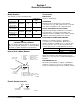
Section 1 General Information Model Numbers Accessories This manual covers the following models: BIN CASTER Flake Ice Undercounter Self-Contained Air-Cooled Self-Contained Air-Cooled Self-Contained Water Cooled Remote Air-Cooled Chiplet Ice Condensing Unit QF0406A NA NA QF0806A QC0708A NA QF0807W QC0709W NA QF2396N NA RFC2385 Replaces standard legs. ICE BAGGER Maximize profits from bagged ice sales with this convenient accessory.
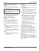
General Information Section 1 Model/Serial Number Location These numbers are required when requesting information from your local Manitowoc distributor, service representative, or Manitowoc Ice, Inc. Record the model and serial number of your ice machine in the space provided below. SV2019 The model and serial number are listed on the OWNER WARRANTY REGISTRATION CARD. They are also listed on the MODEL/SERIAL NUMBER DECAL affixed to the ice machine head section and condensing unit.
Section 1 General Information Owner Warranty Registration Card EXCLUSIONS GENERAL The following items are not included in the ice machine’s warranty coverage: The packet containing this manual also includes warranty information. Warranty coverage begins the day the ice machine is installed. Important Complete and mail the OWNER WARRANTY REGISTRATION CARD as soon as possible to validate the installation date.
General Information Section 1 RESIDENTIAL ICE MACHINE LIMITED WARRANTY WHAT DOES THIS LIMITED WARRANTY COVER? Subject to the exclusions and limitations below, Manitowoc Ice, Inc.
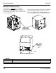
Section 2 Installation Instructions Ice Machine Dimensions These instructions are provided to assist the qualified installer. Check your local Yellow Pages for the name of the nearest Manitowoc distributor, or call Manitowoc Ice, Inc. for information regarding start-up services. QF400 AIR COOLED ICE MACHINE QC700/QF800 WATER COOLED ICE MACHINE 11.13” (28.3 CM) 19” (48.2 CM) 26” (66 CM) 1.9” (4.8 CM) 2” (5.1 CM) 26.5” (67.3 CM) 7.2” (18.2 CM) 3.04” (7.72 CM) 32.5” (82.55 CM) 13.5” (34.3 CM) 3.
Installation Instructions Section 2 Ice Machine Head Section and Remote Condensing Unit Dimensions QF2300 HEAD SECTION AND RFC2385 REMOTE CONDENSING UNIT 24.5” (62.23 CM) 30” (76.2 CM) 24.13” (53.7 CM) 34” (86.4 CM) 2.25” (5.72 CM) 4.5” (11.43 CM) 25.75” (65.4 CM) 23.5” (67.3 CM) 14.5” (36.8 CM) 14.5” (36.8 CM) SV1784 2.8” (7.12 CM) 1.8” (4.6 CM) 9.8” (24.89 CM) 2-2 9.5” (24.1 CM) 10.75” (27.
Section 2 Installation Instructions Ice Storage Bin Dimensions 22 INCH (56 CM) ICE STORAGE BINS 48 INCH (130 CM) ICE STORAGE BINS SV1614 SV1297 Bin Model B320 B420 Dimension A 34.0 in (86.3 cm) 34.0 in (86.3 cm) Dimension B 32.0 in (81.3 cm) 44.0 in (111.7 cm) 30 INCH (76 CM) ICE STORAGE BINS B970 SV1609 Bin Model B170 B400 B570 Dimension A 29.5 in (74.9 cm) 34.0 in (86.3 cm) 34.0 in (86.3 cm) Part Number 000002688 Dimension B 19.1 in (48.5 cm) 32.0 in (81.3 cm) 44.0 in (111.
Installation Instructions Section 2 Large Capacity Ice Storage Bin Dimensions 30 INCH (76 CM) ! Warning A 34” (86.4 cm) B All Manitowoc ice machines require the ice storage system (bin, dispenser, etc.) to incorporate an ice deflector. Manitowoc ice machines require adding Manitowoc Ice Deflector Kit when installing with non-Manitowoc ice storage systems.
Section 2 Installation Instructions Location of Ice Machine Ice Machine Heat of Rejection The location selected for the ice machine must meet the following criteria. If any of these criteria are not met, select another location. • The location must be free of airborne and other contaminants. • The air temperature must be at least 45°F (7°C), but must not exceed 110°F (43.4°C). • The water temperature must be at least 45°F (7°C), but must not exceed 90°F (32.2°C).
Installation Instructions Section 2 Leveling the Ice Storage Bin Condenser Air Baffle 1. Screw the leveling legs onto the bottom of the bin. (QC700/QF800 Air-Cooled Ice Machines Only) 2. Screw the foot of each leg in as far as possible. The air-cooled baffle prevents condenser air from recirculating. To install: ! Caution The legs must be screwed in tightly to prevent them from bending. 1. Remove the back panel screws next to the condenser. 2.
Section 2 Installation Instructions Electrical Service ! Warning All wiring must conform to local, state and national codes. ! Warning The ice machine must be grounded in accordance with national and local electrical codes. VOLTAGE TOTAL CIRCUIT AMPACITY The maximum allowable voltage variation is ±10% of the rated voltage on the ice machine model/serial number plate at start-up (when the electrical load is highest).
Installation Instructions Section 2 Electrical Requirements Ice Machine Head Section Air-Cooled Ice Machine Voltage Phase Cycle Maximum Fuse/Circuit Breaker Minimum Circuit Amps Total Circuit Amps Remote Air-Cooled Maximum Minimum Fuse/ Circuit Circuit Amps Breaker NA NA Water Cooled Maximum Fuse/Circuit Breaker Minimum Circuit Amps NA NA QF400 115/1/60 15 NA 9.8 Before Serial Number 110638713 230/1/50 15 NA 4.2 NA NA NA NA QF400 115/1/60 15 NA 6.
Section 2 Installation Instructions Ice Machine Head Section Electrical Wiring Connections QC700C/QF800C ICE MACHINE HEAD SECTION ! Warning These diagrams are not intended to show proper wire routing, wire sizing, disconnects, etc., only the correct wire connections. 230/1/50 L1 All electrical work, including wire routing and grounding, must conform to local, state and national electrical codes.
Installation Instructions Section 2 Remote Electrical Wiring Connections ! Warning These diagrams are not intended to show proper wire routing, wire sizing, disconnects, etc., only the correct wire connections. All electrical work, including wire routing and grounding, must conform to local, state and national electrical codes. Though wire nuts are shown in the drawings, the ice machine field wiring connections may use either wire nuts or screw terminals.
Section 2 Installation Instructions Water Supply and Drains DRAIN CONNECTIONS POTABLE WATER SUPPLY Follow these guidelines when installing drain lines to prevent drain water from flowing back into the ice machine and storage bin: Local water conditions may require treatment of the water to inhibit scale formation, filter sediment, and remove chlorine odor and taste. • Drain lines must have a 1.5 inch drop per 5 feet of run (2.5 cm per meter), and must not create traps.
Installation Instructions Section 2 WATER SUPPLY AND DRAIN LINE SIZING/CONNECTIONS ! Caution Plumbing must conform to state and local codes. Location Water Temperature Water Pressure Ice Machine Fitting Ice Making Water Inlet 45°F (6°C) Min. 90°F (32.2°C) Max. 33°F (0.6°C) Min. 90°F (32.2°C) Max. 20 psi (137.9 kPA) Min. 80 psi (551.5 kPA) Max. 20 psi (137.9 kPA) Min. 150 psi (1034.2 kPA) Max. 3/8" Female Pipe Thread Tubing Size Up to Ice Machine Fitting 3/8" (9.
Section 2 Installation Instructions Refrigeration System Installation Factory Equipment Refrigeration Amounts (QF2300/RFC2385 ONLY) ICE MACHINE HEAD SECTION QuietQube® Ice Machine Remote Single Circuit Condenser Line Set* RFC2300 RFC2385 RC-20 RC-30 RC-50 Line Set Suction Line Liquid Line RC 20/30/50 3/4 inch (19.1 mm) 1/2 inch (12.
Installation Instructions Section 2 Refrigeration Line Set Installation GENERAL A. LINE SET LENGTH Refrigeration line set installations consist of vertical and horizontal line set distances between the ice machine and the condensing unit. The following guidelines, drawings and calculation methods must be followed to assure proper oil return and condensing unit/ice machine operation.
Section 2 Installation Instructions C. SUCTION LINE OIL TRAPS ! Caution Do not form unwanted traps in refrigeration lines. Never coil excess refrigeration tubing. 0 to 20 feet (0 to 6.1 m) Rise: The ice machine head section has one oil trap built in which allows for a maximum condenser rise of 20 feet (6.1 m) without additional traps in the suction line. 21 to 35 feet (6.4 to 10.7 m) Rise: The suction line requires an additional Oil Trap (“S” type) to be installed.
Installation Instructions Section 2 Step 4 Connecting the line set. To prevent oxidation of the copper, purge line set and condensing unit with dry nitrogen while brazing. Connect The Line Set To The Ice Machine Head Section ! Warning The ice machine head section contains refrigerant charge. The ice machine head section contains three (3) refrigeration valves that must remain closed until proper installation of the line sets is completed.
Section 2 Installation Instructions Step 5 Pressure Test and Evacuate The Line Set and Remote Condensing Unit Schrader valve core removal tools that allow for removal and installation of the valve cores without removing manifold gauge set hoses are recommended to decrease the evacuation time. Leave the line set shut off valves closed (front seated). Pressure test the line sets and remote condensing unit with 150 psig of dry nitrogen.
Installation Instructions Section 2 Replace cap on receiver service valve and tighten. Leak check the new line set connections at the ice machine head section, condensing unit and S trap as well as all factory joints throughout the entire system. Disconnect power to the remote condensing unit. Place the ICE/OFF/CLEAN toggle switch into the ICE position. This allows the low side and high side pressures to equalize. Place the ICE/OFF/CLEAN toggle switch in the OFF position.
Section 2 Installation Instructions Suction Shut Off Valve Insulation The pre-formed suction shut-off valve insulation is located in the plastic bag taped to the water curtain. A. Verify valve and schrader caps are tightened to specifications (see Step 6). PRE-FORMED INSULATION TIGHTEN VALVE CAPS TO SPECIFICATIONS SV3084 B. Place insulation over schrader valve cap and left side of valve. Position the tab between the mounting bracket and rear panel. PLACE TAB BETWEEN VALVE BODY AND PANEL SV3085 C.
Installation Instructions Section 2 TYPICAL REMOTE SYSTEM INSTALLATION CONDENSING UNIT ELECTRICAL DISCONNECT LIQUID LINE SUCTION LINE ICE MACHINE HEAD SECTION SUCTION REFRIGERANT SHUT-OFF VALVE INTERCONNECTING WIRING (QF2300 ONLY) LIQUID REFRIGERANT SHUT-OFF VALVE SV3021 2-20 Part Number 000002688
Section 2 Installation Instructions Installation Checklist Is the Ice Machine level? Has the toggle switch been placed in the ice position? (Switch is located behind front cover) Has all of the internal packing been removed? Have all of the electrical and water connections been made? Has the supply voltage been tested and checked against the rating on the nameplate? Is there proper clearance around the ice machine for air circulation? Has the ice machine been installed where ambient temperatures will re
Installation Instructions Section 2 Before Starting the Ice Machine All Manitowoc ice machines are factory-operated and adjusted before shipment. Normally, new installations do not require any adjustment. To ensure proper operation, follow the Operational Checks in Section 3 of this manual. Starting the ice machine and completing the Operational Checks are the responsibilities of the owner/operator. The float valve setting must be checked to verify it is correctly set.
Section 3 Ice Machine Operation Component Identification ICE MACHINE HEAD SECTION QC700/QF800 QUARTER TURN THUMBSCREWS WATER LEVEL PROBE CLEANING SOLUTION FILL HOLE CONDENSER AIR FILTER DUMP VALVE WATER FLOAT VALVE COIL CONDENSER FAN MOTOR POTABLE WATER INLET ICE CHUTE ICE/OFF/CLEAN TOGGLE SWITCH WATER INLET QUICK DISCONNECT FITTING GEARMOTOR POTABLE WATER DRAIN SV2019 SV2022 QF400 WATER FLOAT VALVE COIL WATER LEVEL PROBES EVAPORATOR WATER INLET QUICK DISCONNECT ICE CHUTE CONTROL BOX DUMP V
Ice Machine Operation Section 3 QF2300 CLEANING SOLUTION FILL HOLE ICE CHUTE RETAINING CLAMP EVAPORATOR ELECTRICAL COMPARTMENT CONDENSER FAN MOTOR AIR CONDENSER ICE/OFF/ CLEAN TOGGLE SWITCH ICE CHUTE GEAT MOTOR/ GEAR BOX ASSEMBLY WATER LEVEL PROBES SUCTION FILTER FLOAT VALVE COMPRESSOR HEAD PRESSURE CONTROL VALVE ICE CHUTE ELBOW SV2100 RFC2385 Remote Condensing Unit DUMP VALVE SV2102 CLEANING SOLUTION FILL HOLE 3-2 WATER RESERVOIR Part Number 000002688
Section 3 Ice Machine Operation Operational Checks GENERAL WATER LEVEL CHECK Manitowoc ice machines are factory-operated and adjusted before shipment. Normally, a newly installed ice machine does not require any adjustment. The float valve maintains the correct water level. The water level must allow the water level probes to maintain water contact throughout the freeze cycle. The water level is factory set and normally will not require adjustment. Check the water level during the freeze cycle.
Ice Machine Operation Section 3 Interior Cleaning and Sanitizing GENERAL You are responsible for maintaining the ice machine in accordance with the instructions in this manual. Maintenance procedures are not covered by the warranty. Manitowoc Ice Machines have three separate cleaning procedures. Clean and sanitize the ice machine every six months for efficient operation.
Section 3 Ice Machine Operation 3. Shine a flashlight through the condenser to check for dirt between the fins. If dirt remains: CLEANING THE CONDENSER ! Warning Disconnect electric power to the ice machine and the remote condenser at the electric service switch before cleaning the condenser. Air-Cooled Condenser (SELF-CONTAINED AND REMOTE MODELS) A. Blow compressed air through the condenser fins from the inside. Be careful not to bend the fan blades. B. Use a commercial condenser coil cleaner.
Ice Machine Operation Section 3 MANITOWOC’S CLEANING TECHNOLOGY Manitowoc Flake/Chiplet Ice Machines include technology that allows the initiation and completion of a cleaning or sanitizing cycle at the flip of a switch. This cycle will permit cleaning of all surfaces that come in contact with the water distribution system. Periodic maintenance must be performed that includes sanitizing the bin and adjacent surface areas, which are not contacted by the water distribution system.
Section 3 Ice Machine Operation PREVENTATIVE MAINTENANCE CLEANING PROCEDURE QF400 Use Ice machine cleaner part number 000000084 only. This cleaner is used to remove lime scale or other mineral deposits. It is not used to remove algae or slime. Refer to “Cleaning/Sanitizing Procedure” for removal of algae and slime. To initiate a cleaning cycle using Manitowoc’s Cleaning Technology use the following procedure. Step 1 Set the toggle switch to the OFF position.
Ice Machine Operation Section 3 CLEANING/SANITIZING PROCEDURE QC700/QF800/QF2300 Use Ice machine cleaner part number 000000084. Use Ice machine sanitizer part number 94-0565-3. Step 1 Remove front and top covers and set the toggle switch to the OFF position. Step 2 Remove all ice from the bin. Step 3 Disconnect water supply line at float valve quick disconnect by depressing stainless steel lever. Step 4 Remove the top cover from water reservoir.
Section 3 Ice Machine Operation CLEANING/SANITIZING PROCEDURE QF400 Use Ice machine cleaner part number 000000084. Use Ice machine sanitizer part number 94-0565-3. Step 1 Set the toggle switch to the OFF position and remove all ice from the bin. Step 2 Remove the 2 thumbscrews and white plastic panel. Step 17 Remove the water level probes from the top cover and with the wires attached, place the water level probes (stand upright) inside the water reservoir.
Ice Machine Operation Section 3 PROCEDURE TO CLEAN HEAVILY SCALED FLAKE/CHIPLET ICE MACHINES QF400/QC700/QF800/QF2300 Step 4 Refer to chart below: Step 5 Remove all water from the evaporator and water reservoir. Start an ice making cycle by moving the toggle switch to the ICE position. Water will flow through the water dump valve and down the drain for 45 seconds. After 45 seconds move the toggle switch to the OFF position. Remove the plug from the top cover of the water reservoir.
Section 3 Ice Machine Operation REMOVAL OF PARTS FOR CLEANING/SANITIZING ! Warning Disconnect electric power to the ice machine at the electric switch box before proceeding. ! Warning Wear rubber gloves and safety goggles (and/or face shield) when handling Ice Machine Cleaner or Sanitizer. 3. Soak the removed part(s) in a properly mixed solution of cleaner and water. Solution Type Cleaner Water 1 gal. (4 l) Mixed With 16 oz (500 ml) cleaner Part Number 000000084 4.
Ice Machine Operation Section 3 Water Level Probe Removal Water Reservoir Cover Removal QF400/QC700/QF800/QF2300 1. Place the toggle switch in the OFF position, turn off the water supply and disconnect electrical power to the ice machine. Water Level Probe Removal 1. Place the toggle switch in the OFF position, turn off the water supply and disconnect electrical power to the ice machine. 2. Remove water level probes. 2.
Section 3 Ice Machine Operation Float Valve Removal Water Reservoir Cover Removal QF2300 1. Place the toggle switch in the OFF position, turn off the water supply and disconnect electrical power to the ice machine. 2. Remove water level probes. 1. Place the toggle switch in the OFF position, turn off the water supply and disconnect electrical power to the ice machine. 2. Disconnect water supply line at float valve quick disconnect by depressing stainless steel lever. 3. Remove water float valve coil. 3.
Ice Machine Operation Section 3 Ice Diverter Removal Water Reservoir Removal 1. Place the toggle switch in the OFF position and turn off the water supply to the ice machine at the water service valve. 2. Disconnect water supply line at float valve quick disconnect by depressing stainless steel lever. 3. Place the toggle switch in the ICE position. The dump valve will open and the float reservoir will empty. 4.
Section 3 Ice Machine Operation Ice Chute Removal QF2300 QC700/QF800 1. Follow steps to remove float reservoir. 2. The ice chute and ice chute grommet will be removed as a unit. Pull forward on the top of the ice chute, and slide the ice chute and grommet off the end of the evaporator spout. 1. Place the toggle switch in the OFF position, turn off the water supply and disconnect electrical power to the ice machine. 2. Remove ice chute retaining clamp from top of evaporator. 3.
Ice Machine Operation Section 3 Bin Door Removal Cabinet Removal QF0400 QF0400 Door removal allows easier access for cleaning and sanitizing. 1. Remove all ice from bin and disconnect power. 2. Remove thumbscrews and evaporator panel. 1. Disconnect the electrical power to the ice machine and remove ice from bin. 3. Remove three screws from the bottom of the left and right side of cabinet. 2. Grasp the rear of the bin door and pull bin door forward approximately 5”. 4.
Section 3 Ice Machine Operation Water Dump Valve The water dump valve normally does not require removal for cleaning. To determine if removal is necessary: 1. Locate the water dump valve. 2. Set the toggle switch to ICE. 3. While the ice machine is in the freeze mode, check the water trough to determine if the dump valve is leaking. If there is no or little water in the water trough (during the freeze cycle) the dump valve is leaking.
Ice Machine Operation Removal from Service/Winterization Section 3 WATER COOLED CONDENSING UNIT GENERAL 1. Perform steps 1-6 in previous column. Special precautions must be taken if the ice machine head section is to be removed from service for an extended period of time or exposed to ambient temperatures of 32°F (0°C) or below. 2. Disconnect the incoming water and drain lines from the water-cooled condenser. 3. Insert a large screwdriver between the bottom spring coils of the water regulating valve.
Section 4 Ice Machine Sequence of Operation QF400/QC700/QF800 PRIOR TO START-UP AUTOMATIC SHUT-OFF When the toggle switch is placed in the “ice” position the following must occur prior to starting an ice making cycle. 3A. Ice Run Out A. The bin level probe must be open (bin level light off). If the probe is closed, (bin level light on) when the toggle switch is moved to ICE, the control system waits until the bin level probe opens, (bin level light off) before starting an ice making sequence.
Ice Machine Sequence of Operation Section 4 QF2300 PRIOR TO START-UP AUTOMATIC SHUT-OFF When the toggle switch is placed in the “ice” position the following must occur prior to starting an ice making cycle. 3A. Ice Run Out A. The bin level probe must be open (bin level light off). If the probe is closed, (bin level light on) when the toggle switch is moved to ICE, the control system waits until the bin level probe opens, (bin level light off) before starting an ice making sequence.
Section 5 Before Calling Service Checklist If a problem arises during operation of your ice machine, follow the checklist below before calling for service. Routine adjustments and maintenance procedures are not covered by the warranty. Problem Ice machine does not operate. Possible Cause No electrical power to the ice machine. Control Board fuse open ICE/OFF/CLEAN toggle switch set improperly. 8 minute lockout has not expired. Bin level sensor is disconnected or is contacting the ice.
Before Calling Service Section 5 Safeguard Feature In addition to standard safety controls, your Manitowoc ice machine features built-in SafeGuards. The ice machine will stop when conditions arise that would cause major component failure. RESET PROCEDURE SAFEGUARD INDICATOR LIGHTS 1. Move the ICE/OFF/CLEAN toggle switch to OFF and then back to ICE. During a SafeGuard Mode the corresponding light (disch temp, water level or speed) will flash continuously. A.
Section 5 Analyzing Why SafeGuards May Stop the Ice Machine According to the refrigeration industry, a high percentage of compressor failure are the result of external causes. These can include flooding or starving expansion valves, dirty condensers, water loss to the ice machine, etc. SafeGuards protect the ice machine (primarily the compressor) from external failures by stopping ice machine operation before major component damage occurs.
Before Calling Service Section 5 Gear Motor Speed Anytime the motor speed sensor detects the motor speed (rpm) is below the minimum range for 3 continuous seconds, the ice machine will: During the SafeGuard Mode the Motor Speed Sensor light will continually flash to indicate a SafeGuard Mode. The ice machine remains off until: 1. De-energize the compressor and/or gear motor. • The toggle switch is moved from OFF to ICE. 2. Continuously flash the Gear Motor Speed light.
Section 5 Before Calling Service Temperature is Too High or Low QF400/QC700/QF800 4. After 30 minutes of compressor run time, the ice machine will check the discharge line temperature. The temperature sensor (thermistor) is mounted on the compressor discharge line. The temperature sensor provides input to the control board. The control board monitors the temperature anytime the compressor is energized. Discharge line temperature normal: The ice machine continues to make ice.
Before Calling Service Section 5 THIS PAGE INTENTIONALLY LEFT BLANK 5-6 Part Number 000002688
Manitowoc Ice, Inc. 2110 South 26th Street P.O. Box 1720 Manitowoc, WI 54221-1720 Phone: (920) 682-0161 Service Fax: (920) 683-7585 Web Site - www.manitowocice.com Manitowoc Foodservice International S.A.S. 18 Chemin de Charbonnières F-69132 Ecully Cedex Téléphone : +33 (0)4 72 18 22 50 Fax : +33 (0)4 72 18 22 60 Site Web – www.manitowocice.com Manitowoc (China) International Refrigeration Company, LTD No. 151 Jiam Ye Road Hangzhou Hi-Tech Industry Development Zone (Bin Jiang) Hangzhou, Zhejiang 310052 P.