V-Cube Slim™ Split Floor-by-Floor Cooling Systems Installation, Operation & Maintenance Manual Sizes: 830 and 840 Model: F-Series MAMM-VCS-IOM-3FA (September 2013) PN 71144924
Contents Nomenclature........................................................................................................................3 Introduction............................................................................................................................4 Warnings, Cautions and Notices...........................................................................................4 Receiving Inspection and Storage............................................................................
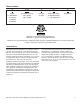
Nomenclature F 830 S H F Voltage Size (BTUH Cooling) Unit Type Temperature Range Design Series F = 208-230/3/60 830 = 732,000 S = Split H = Standard Range G = 460/3/60 840 = 732,000 L = Low Temperature J = 380/3/50 K = 575/3/60 “Mammoth” is a registered trademark of Mammoth, Inc. ©Mammoth, Inc. All rights reserved throughout the world. Illustrations cover the general appearance of Mammoth products at the time of publication. Mammoth, Inc.
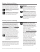
Warnings, Cautions and Notices Warnings, cautions and notices appear at appropriate locations throughout this manual. Your personal safety and the proper operation of this machine depend upon the strict observance of these precautions. Read this manual thoroughly before operating or servicing this unit. General Warnings WARNING! Indicates a potentially hazardous situation which, if not avoided, could result in death or serious injury.
Disassembly and Assembly IMPORTANT! All blower wiring is correctly phased at the factory and must be re-wired correctly upon re-assembly for correct compressor and blower operation. Mark all wires and pull through knockouts using care not to scrape the insulation of the wiring when separating sections. If the wire insulation or wire jacket is torn during the disassembly/ re-assembly procedure, replace the wire. Do not use wire that is missing insulation.
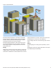
Figure 2: Exploded View End piping assembly FANWALL section Main chassis Main electrical panel Coil cabinet Mechanical lifting equipment is necessary to dismantle and relocate the V Cube Slim Split. This unit will weigh between 4000 and 5800 pounds depending on options and features built into the unit at the factory. Mechanical lifting equipment is also required to remove the sub assemblies from the main chassis. Subassemblies weigh a minimum of 205 pounds and as much as 1500 pounds each.
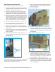
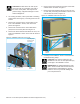
Main Electrical Panel Removal The main electrical panel is removed as follows. 1. Unplug the wiring harness that connects the EPiC™ keypad, reset buttons and selector switches from the panel door to the main electrical panel. 2. Remove the panel door by lifting it from its hinges. Carefully set it away from the unit to help prevent damage during the remaining disassembly process. 1. Remove all access panels and set them aside. See Figure 4. Quarter turn, twist lock fasteners secure most access panels.
Figure 6: Front Side Piping Disconnects IMPORTANT! Filter rack mounting bolts are a specific length so as to not contact the coil behind the bulkhead. If any are lost, replacement bolts must be the same length. 2. If still in place, remove the coil cabinet inner access panel from the side of the cabinet. 3. Remove the six fasteners (three on each side) connecting the sides of the coil cabinet to the main chassis. 4.
CAUTION! DO NOT lift the fan cells by the motor eye bolts or by attaching eye bolts to the motor mount plates. This may result in personal injury, equipment damage or motor/ wheel misalignment. 2. As a safety precaution, take up the slack in the lifting straps before removing any connecting bolts from the section. 6. Remove the access panel from the back of the base cabinet section as shown in Figure 9. 7.
Installation WARNING! The installer must determine and follow all applicable codes and regulations. This equipment presents hazards of electricity, rotating parts, sharp edges, heat and weight. Failure to read and follow these instructions can result in property damage, severe personal injury or death. This equipment must be installed by experienced, trained personnel only. General To prevent damage, this equipment should not be operated for supplementary heating and cooling during the construction period.
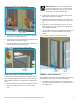
Figure 12: Clearances - Units Without Waterside Economizer FILTER ACCESS FILTER ACCESS 42.0 [1067] SERVICE CLEARANCE 36.0 [914] 36.0 [914] SERVICE CLEARANCE Ductwork and Attenuation Discharge ductwork is normally used with the V-Cube Slim™. Return air ductwork may also be required. All ductwork should conform to industry standards of good practice as described in the ASHRAE Systems Guide.
pipe fitting to accommodate the condensate drain connection. 10. Flush the system for at least two hours, or longer if required, until the drain water is clear and clean. Do not locate any point in the drain system above the drain connection of any unit. 11. Shut off the supplemental heater (if applicable) and the circulator pump. The condensate piping system must be vented at its highest point. 12. Open all drains and vents to completely drain down the system. . Cleaning and Flushing 13.
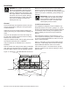
Figure 13: Electrical Connection Points Field control wiring Operating Voltage Incoming power supply must comply with the data in Table 1. Unit operation outside of the Min/Max range is not recommended and will result in premature component failure. Table 1: Operating voltages Power wiring .
Startup WARNING! Electric shock and moving equipment hazard. Can cause severe injury or death. Lock and tag out all electric power before carrying out these procedures. More than one disconnect may be required to deenergize the unit.. The following should be used as a guide for a comprehensive commissioning and startup procedure which is required before placing your Mammoth unit into service.
Control Settings • Verify that all control jumper positions, time delay relay settings, baud rates and control temperatures and/or pressure settings match those indicated on the electrical wiring diagram, as applicable. Refer to the wiring schematics provided with your unit for locations and settings. Startup: Power On With the main power control panel door closed, switch on the main power to the unit. Then carry out the following procedures. WARNING! Electric shock and moving equipment hazard.
Blowers and Fans 2. Turn the unit system switch to the on position. Switch the motor protectors for the supply air fans to the On position (see page 6 for motor protector locations). Turn the system switch to the On position, then carry out the following checks: 3. Verify that the liquid sub-cooling is between 10 and 12 degrees F (8 to 10 degrees F for shell and tube or flat plate condensers). • • Verify that the unit controller is calling for the unit to operate.
Chilled Water, Hot Water and Steam Coils Startup Visually check the coils and system piping for proper installation and any signs of leakage. Repair as needed. Check motorized valves and linkages for the following points of operation. Controls Startup For controls startup procedures, see the EPIC® Sequence of Controls documentation that is included in the packet of information that is zip-tied to the inside of the main control panel.
Troubleshooting The charts in this section provide general guidelines on troubleshooting problems with your V-Cube Slim unit. If Service assistance is required contact Mammoth Service at (952) 358-6618. For additional help diagnosing prob- lems or servicing the unit, contact your local Mammoth representative. For assistance locating your Mammoth representative, call 952-358-6600 or e-mail info@mammoth-inc.com.
Electrical Terminal Tightening Torques The following tables provide tightening torques, as recommended by the component manufacturer, for many of the electrical components provided on Mammoth units. If a torque value is provided on the component, use that value instead. Where no torque value is given or provided here, use the torques provided in the tables at the end of this section, which are taken from UL Standard 486A.
Table 5: Square D Molded Case Circuit Breakers – Mechanical lug kit wire ranges and torques Lug Mounting Screw Torque Wires Per Lug and Wire Ranges Wire Binding Screw Torque Lug Kit Lugs Per Kit Circuit Breaker Wires Domestic Metric Lb-in. N•m Wire* Lb-in. N•m AL50FA 3 FA, FH, FI 1 #14–#4 Cu or #12–#4 Al 2.5–25 mm2 4–25 mm2 40 4.5 Cu #14–#4 STR/ SOL Al #12–#4 STR Al #12–#10 SOL 35 35 15 4.0 4.0 1.7 AL100FA4 3 FC 1 #14–#3 Cu or #12–#1 Al 65 7.
Conductor size installed in connector Slotted head No. 10 or larger* Hexagonal head - external drive socket wrench AWG or kcmil (mm2) Slot width to 3/64 inch (1.2 mm) or slot length to 1/4 inch Slot width – over 3/4 inch (1.2 mm) or slot length over 1/4 inch Split-bolt connectors Other connectors 30 – 10 (0.05 – 5.3) 20 (2.3) 35 (4.0) 80 (9.0) 75 (8.5) 8 -8.4 25 (2.8) 40 (4.5) 80 (9.0) 75 (8.5) 6–4 (13.3 – 21.2) 35 (4.0) 45 (5.1) 165 (18.6) 110 (12.4) 3 -26.7 35 (4.0) 50 (5.
Unit CheckoutV-Cube Sheet Slim Unit Checkout Sheet Customer Data Customer Name ________________________________________ Date _________________________________________ Address ________________________________________________________________________________________________ Phone ________________________________________________ Unit Number___________________________________ Unit Nameplate Data Make _______________________ Model Number ________________________ Serial Number _______________________ Compressor
Mammoth V-Cube Slim Split IOM, MAMM-VCS-IOM-3FA (September 2013) 23
info@mammoth-inc.com www.mammoth-inc.com Mammoth, Inc. has a policy of continuous improvement and reserves the right to change design and specifications without notice. © 2013 Mammoth, Inc.