
User guide


11
MAMM-VCS-IOM-1EB (October 2011)
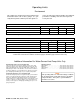
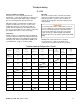
Operating Limits
APPLICATIONLIMITS
WATERTEMPERATURES/DegreesF*
Standardrange LowTempGeothermal
COOLING HEATING COOLING HEATING
MINIMUMENTERINGFLUIDTEMPERATURE
50˚ 50˚ 40˚ 25˚
MAXIMUMENTERINGFLUIDTEMPERATURE
110˚ 90˚ 110˚ 90˚
*Applicationlimitsapplyatorabovestandardflowratesspecifiedforsizeofunit.
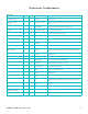
APPLICATIONLIMITS
AIRTEMPERATURES/DegreesF*
Standardrange LowTempGeothermal
COOLING HEATING COOLING HEATING
MINIMUMAMBIENTAIRTEMPERATURE**
50˚ 50˚ 50˚ 50˚
MAXIMUMAMBIENTAIRTEMPERATURE**
110˚ 110˚ 110˚ 110˚
MINIMUMENTERINGAIRTEMPERATURE
65˚ 50˚ 65˚ 40˚
MAXIMUMENTERINGAIRTEMPERATURE
100˚ 80˚ 100˚ 80˚
*Applicationlimitsapplyat
orabovestandardflowratesspecifiedforsizeofunit.
**Minimumandmaximumambientconditionsapplytoductedsupplyandreturnunitsonly.
Environment
This equipment is designed for indoor installation only.
Sheltered locations such as attics, garages, etc., gen-
erally will not provide sufficient protection against ex-
tremes in temperature and/or humidity, and equipment
performance, reliability, and service life may be ad-
versely affected.
Standard range water source heat pump units
Units are designed to start-up in an ambient of 50°F (10°C), with
entering air at 50°F (10°C), with entering fluid at 70°F (21°C), with
both air and fluid flow rates used in the ISO 13256-1 rating test, for
initial start-up in winter. Note that this is not a normal or continuous
operating condition. It is assumed that such a start-up is for the pur-
pose of bringing the building space up to occupancy temperature.
Geothermal range water source heat pump units
Geothermal heat pump units are designed to start-up in an ambient
of 40°F (5°C), with entering air at 40°F (5°C), with entering fluid at
25°F (-4°C), with both air and fluid at flow rates used in the ISO
13256-1 rating test, for initial start-up in winter. Note that this is not a
normal or continuous operating condition. It is assumed that such a
start-up is for the purpose of bringing the building space up to occu-
pancy temperature.
Operating voltages
208-230/60/3 . . . . . . . . . . . . . . . . . . . . 197 volts min.; 253 volts max.
460/60/3 . . . . . . . . . . . . . . . . . . . . . . . . 414 volts min.; 506 volts max.
380-415/50/3. . . . . . . . . . . . . . . . . . . . ..342 volts min.; 418 volts max
575/60/3. . . . . . . . . . . . . . . . . . . . . . . . .515 volts min.; 632 volts max.
Additional Information For Water Source Heat Pump Units Only
Note:
Units operating with over- and under-voltage conditions
for extended periods of time will experience premature
component failure. Three phase system imbalance
should not exceed 2%.