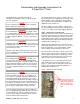
V-Cube Slim™ Floor-by-Floor Cooling and Heat Pump System Installation, Operation and Maintenance Manual Sizes: 180 to 840 Model: E Series ©2011 Mammoth, Inc.
Table of Contents Model Nomenclature ··················································································································3 Transportation and Storage ········································································································3 Installation ··································································································································4 Unit Location ···································································
Model Nomenclature F -180- V- H- E Design Series Voltage BTU/hr Cooling Unit Type Temperature Range F = 208-230/60/3 180 = 180,000* V = Vertical H = Standard Range G = 460/60/3 240 = 240,000 J = 380-415/50/3 280 = 280,000* K = 575/60/3 310 = 310,000 L = Low Temperature 350 = 350,000* 460 = 460,000 530 = 530,000* 630 = 630,000 700 = 700,000* 830 = 830,000 840 = 840,000* *Air handler configuration available.
Installation General IMPORTANT: Mammoth V-Cube Slim™ units should be installed only by qualified personnel, experienced in the installation of this equipment and related systems. Read these instructions carefully before unpacking, installing and operating this unit 1. To prevent damage, this equipment should not be operated for supplementary heating and cooling during the construction period. 2.
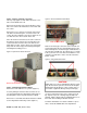
Disassembly and Assembly Instructions For V-Cube Slim™ Units V-Cube Slim units are designed to allow for installation in new facilities and as a retrofit for older, obsolete equipment. NOTE: Please read all disassembly instructions completely before starting any disassembly DANGER! A mechanical lift is required to move or lift all sections of a V-Cube Slim™ unit. Do not attempt to move or lift sections without a mechanical lift.
Step 2 – Remove optional coil section This step only applies to units with a waterside economizer or hot/chilled water coil. Figure 3—Removal of Blower Section Bolts Remove the bolts that connect the welded base of the water coil section to the welded base of the main cabinet section. Remove the access panels on each side of the water coil cabinet shown in Figure 2. Inside the water coil section, disconnect wiring to any valves and/or air sensors that run to the other sections in the unit.
Ductwork and Attenuation Discharge ductwork is normally used with the V-Cube Slim™. Return air ductwork may also be required. All ductwork should conform to industry standards of good practice as described in the ASHRAE Systems Guide. The discharge duct system will normally consist of a flexible connector at the unit connection, a transition piece to the full duct size, a short run of duct, and elbow with vanes, and a trunk duct teeing into a branch duct with discharge diffuses.
Supply Piping 1. All units should be connected to supply and return piping in a two-pipe reverse return configuration. A reverse return system is inherently self-balancing and requires only trim balancing where multiple quantities of heat pumps with different flow and pressure drop characteristics exist in the same loop. Check for proper water balance by measuring differential temperature reading across the water connections. 2. The piping may be steel, copper or PVC.
Cleaning and Flushing 1. Prior to first operation of the V-Cube Slim™, the water circulation system must be cleaned and flushed of all construction dirt and debris. 2. If the unit is equipped with water shutoff valves, either electric or pressure operated, the supply and return run-outs must be connected at each unit location. This will prevent the introduction of dirt into the unit. 3. Fill the system with water with all air vents open.
Start-up 1. Open all valves to the full open position and turn on power to the V-Cube Slim™. 2. Set room temperature sensor for “Fan Only” operation by selecting “Off” at the system switch and “On” at the fan switch. If “Auto” fan operation is selected, the fan will cycle with the compressor. Check for proper air delivery. 3. A 5 minute anti-short cycle delay is inherent to the unit’s microprocessor board. After the 5 minute delay, check the discharge air temperature using the unit keypad. 4.
Operating Limits Environment This equipment is designed for indoor installation only. Sheltered locations such as attics, garages, etc., generally will not provide sufficient protection against ex- tremes in temperature and/or humidity, and equipment performance, reliability, and service life may be adversely affected.
Mammoth EPiC™ Systems I/O Flex 6126 The standard factory-integrated DDC controller provides control flexibility that can be easily customized to meet any sequence of operation needs. It is fully capable of operating in a 100% stand-alone mode or can connect to a Building Automation System (BAS) using any of today’s four leading protocols: BACnet, Modbus, N2, and Lontalk. The base controller provides 12 inputs and 12 outputs plus supports the 8160 expander module if additional inputs/outputs are required.
Examples of I/O’s INPUTS Point UD #1 Description +Pulse BMS Supply Air, Duct Static Reset or Room Air Temperature Setpoint Room Air Temperature UD #2 UD #3 RTD/Therm/Dry System Switch Emergency Shut Down Remote Start UD #4 Contact, 0-10VDC, High Static Low Static VFD in Bypass UD #5 0-20MA Economizer Lockout Cooling Lockout Heating Lockout UD #6 Supply Fan Status Compressor Fault Condensate Overflow UD #7 Duct Static Pressure or Airflow Switch UD #8 Filter Static Pressure or Dirty F
Mammoth EPiC™ Systems Keypad Locally access controllers and operational properties with the easy-to-use BACview6 keypad/display. It plugs into an Rnet connection on a 6126 controller and allows you to display and modify properties. The BACview6 features a numeric keypad, directional keys, and four programmable function keys. A large 4-line by 40character backlit LCD display is provided for easy reading even in poor lighting conditions. The device also includes an alarm indicator light.
General Maintenance Normal maintenance on any V-Cube Slim™ unit includes buy may not be limited to: Air filter changes. Air filters must be replaced a minimum of two times per year. A good standard to follow is at the beginning of the heating season and the beginning of the heating season. In certain environments, more frequent filter changes may be required.
Troubleshooting R-410A The In’s and Out’s of R-410A R-410A is a non-ozone depleting blend of two Refrigerants — HFC-125 and HFC-32 in a fifty percent mixture. Refrigerant 410A exhibits higher operating pressure and refrigeration capacity than R-22. Charging Due to the zeotropic nature of R-410A, it should be charged as a liquid. In situations where vapor is normally charged into a system, a valve should be installed in the charging line to flash the liquid to vapor while charging.
Performance Troubleshooting Performance Troubleshooting Heating Cooling Possible Cause Solution Insufficient Capacity X X Dirty Filter Replace or clean Not cooling or heating properly X X Reduced or no air flow Check for dirty air filter and clean or replace, Check fan motor operation and airflow restriction. External static too high? Check static vs.
UNIT CHECK-OUT SHEET Customer Data Customer Name ________________________________________ Date _________________________________________ Address ________________________________________________________________________________________________ Phone ________________________________________________ Unit Number___________________________________ Unit Nameplate Data Make _______________________ Model Number ________________________ Serial Number _______________________ Compressor(s): # 1: RLA_______ LRA _______
Notes
info@mammoth-inc.com www.mammoth-inc.com Mammoth, Inc. has a policy of continuous product improvement and reserves the right to change design and specifications without notice. FANWALL TECHNOLOGY® and FANWALL® are trademarks of Huntair, Inc. This product is covered by one or more of the following U.S. patents (7,137,775; 7,179,046; 7,527,468; 7,597,534) and other pending U.S. or Canadian patent applications and/or foreign patents. © 2011 Mammoth, Inc.