
Installation guide


6
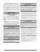
Thermostat
Red
White
Black
Air Handler
Outdoor
Heat
Pump
OUT
IN
R
W
C
O
Y
R
G
C
O
Y
O
C
R
W2
W2
Y1
IN
Green
G
W2
E
ODT
(Optional)
Figure 4. Typical Thermostat Connections
an outside wall or any other location where its operation
may be adversely affected by radiant heat from fireplaces,
sunlight, or lighting fixtures, and convective heat from
warm air registers or electrical appliances. Refer to the
thermostat manufacturer’s instruction sheet for detailed
mounting and installation information.
Voltage unbalance occurs when the voltages of all phases
of a 3-phase power supply are no longer equal. This
unbalance reduces motor efficiency and performance. Some
underlying causes of voltage unbalance may include: Lack
of symmetry in transmission lines, large single-phase loads,
and unbalanced or overloaded transformers. A motor should
never be operated when a phase imbalance in supply is
greater than 2%.
Perform the following steps to determine the percentage of
voltage imbalance:
1. Check the line voltages
of your 3-phase power
supply where it enters the
building and at a location
that will only be dedicated
to the unit installation. (at
the units circuit protection
or disconnect).
EXAMPLE:
AB = 451V
BC = 460V
AC = 453V
2. Determine the average voltage in the power supply.
In this example, the measured line voltages were 451, 460,
and 453. The average would be 454 volts (451 + 460 +
453 = 1,364 / 3 = 454).
3. Determine the maximum deviation:
EXAMPLE
From the values given in step 1, the BC voltage (460V) is
the greatest difference in value from the average:
460 - 454 = 6
454 - 451 = 3
454 - 453 = 1
4. Determine percent of
voltage imbalance by
using the results from step
2 & step 3 in the following
equation.
6
454
100 x
= 1.32%
EXAMPLE
maxvoltage deviation
fromaverage voltage
=100 x
averagevoltage
% Voltage Imbalance
The amount of phase imbalance (1.32%) is satisfactory
since the amount is lower than the maximum allowable 2%.
Please contact your local electric utility company if your
voltage imbalance is more than 2%.
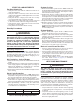
Table 1. Copper Wire Size
COPPER WIRE SIZE — AWG
SUPPLY WIRE LENGTH-FEET
SUPPLY
CIRCUIT
AMPACITY200 150 100 50
6 8 10 14 15
4 6 8 12 20
4 6 8 10 25
4 4 6 10 30
3 4 6 8 35
3 4 6 8 40
2 3 4 6 45
2 3 4 6 50
2 3 4 6 55
1 2 3 4 60
Wire Size based on N.E.C. for 60° type copper conductors.
THERMOSTAT
WIRE GAUGE
MAXIMUM RECOMMENDED
THERMOSTAT WIRE LENGTH (FT)
24 25
22 45
20 70
18 110
Table 2. Thermostat Wire