
Installation guide


4
Connecting Refrigerant Tubing Between
the Indoor & Outdoor Unit
CAUTION:
When servicing, cover or seal openings to
minimize the exposure of the refrigerant system
to air to prevent accumulation of moisture and
other contaminants.
After outdoor and indoor unit placement has been determined,
route refrigerant tubing between the equipment in accordance
with sound installation practices.
• When connecting refrigerant linesets together, it is
recommended that dry nitrogen be flowing through the
joints during brazing. This will prevent internal oxidation
and scaling from occurring.
• Refrigerant tubing should be routed in a manner that
minimizes the length of tubing and the number of bends
in the tubing.
• Refrigerant tubing should be supported in a manner
that the tubing will not vibrate or abrade during system
operation.
• Tubing should be kept clean of foreign debris during
installation.
• Everyeffortshouldbe madebytheinstaller toensure
that the field installed refrigerant containing components
of the system have been installed in accordance with
these instructions and sound installation practices to
insure reliable system operation and longevity.
• Themaximumrecommendedinterconnectingrefrigerant
line length is 75 feet, and the vertical elevation difference
between the indoor and outdoor sections should not
exceed 20 feet.
• Ifpreciseformingofrefrigerantlinesisrequired,acopper
tubing bender is recommended. Avoid sharp bends and
contact of the refrigerant lines with metal surfaces.
• A lter dryer is provided with the unit and must be
installed in the liquid line of the system. If the installation
replaces a system with a filter dryer already present in the
liquid line, the filter dryer must be replaced with the one
supplied with the unit. The filter dryer must be installed
in strict accordance with the manufacturer’s installation
instructions.
• Optionalequipmentsuchasliquidlinesolenoidvalves,
low ambient, etc., should be installed in strict accordance
with the manufacturer’s installation instructions.
Outdoor Orifice Removal & Installation
The orifice installed in the outdoor unit has been sized for use
with the most popularly matched indoor units. Depending
on the indoor coil that the unit is being matched with, the
outdoor restrictor may need to be changed. Please refer
to the Quick Reference Data sheet that is supplied with the
outdoor unit for more information.
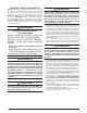
If the outdoor unit has the liquid valve shown in Figure 2, then
the restrictor is located inside the swivel nut connection of
the liquid valve and not inside the outdoor unit’s distributor.
Perform steps 1 - 5 if the outdoor restrictor needs to be
changed.
CAUTION:
When servicing, cover or seal openings to
minimize the exposure of the refrigerant system
to air to prevent accumulation of moisture and
other contaminants.
CAUTION:
To prevent damage to the unit or internal
components, it is recommended that two
wrenches be used when loosening or tightening
nuts. Do not over tighten!
1. Using two wrenches loosen the nut and liquid valve. Turn
the assembly nut counter-clockwise until the orifice body
halves are separated.
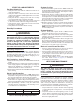
2. Insert a light-gauge wire hook between the valve body
and the restrictor orifice while being careful not to scratch
either part. Carefully remove the restrictor orifice from the
valve body. See Figure 3.
Liquid
Valve
Restrictor
Swivel Nut
Figure 2.
Swivel Nut Adapter
Figure 3. Removal of Orifice