High Efficiency Single Circuit Horizontal and Vertical Water Source Heat Pumps With R-410A Installation, Operation and Maintenance Manual Sizes: 006 to 072 — Horizontal 012 to 072 — Vertical Model: A Vintage MAMM-WSHP-IOM-1AA (September 2011) P/N 71144914
Table of Contents Model Nomenclature ··················································································································3 Transportation and Storage ········································································································3 Installation ··································································································································4 Discharge Conversion—Horizontal Units ···········································
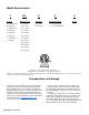
Model Nomenclature F H- H- A BTU/hr Cooling Unit Type Temperature Range Vintage D = 208-230/1/60 06 = 6,000 V = Vertical H = Standard Range E = 265/1/60 009 = 9,000 H= Horizontal F = 208-230/3/60 012 = 12,000 G = 460/3/60 015 = 15,000 J = 380/3/50 018 = 18,000 K = 575/3/60 024 = 24,000 L = 220-240/1/50 030 = 30,000 S = 380/3/60 036 = 36,000 Voltage -024- L = Low Temp Operation 042 = 42,000 048 = 48,000 060 = 60,000 072 = 72,000 “Mammoth” is a registered trademark of Mammoth, I
Installation General IMPORTANT: Mammoth water source heat pumps should be installed only by qualified personnel, experienced in the installation of this equipment and related systems. Read these instructions carefully before unpacking, installing and operating this unit 1. To prevent damage, this equipment should not be operated for supplementary heating and cooling during the construction period. 2.
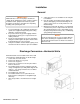
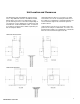
Unit Location and Clearances The diagrams below show minimum suggested clearances. Any additional clearances would be beneficial, but not always necessary. The requirements on any specific unit may increase or be reduced depending on several factors such as maintenance requirements and mechanical or electrical installation codes. If return air is not ducted, enough clearance will be required to provide for adequate airflow.
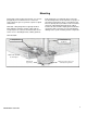
Mounting Vertical units can be mounted on the floor or a concrete pad, typically in a mechanical closet or other area enclosed from the space to promote a quieter occupied environment.. Horizontal, ceiling-hung units are typically installed above hallways and other corridors, away from the occupied space for reduced sound and to allow easier service access. Mounting brackets, rubber grommets, bolts and washers are shipped in place on the unit.
Ductwork and Attenuation Discharge ductwork is normally used with A-vintage horizontal and vertical single circuit units. Return air ductwork may also be required. Horizontal, or ceiling-mounted heat pumps virtually always have discharge ductwork attached to the unit. A flange is provided on the discharge to facilitate attachment of the ductwork. Good design practice requires a flexible connector between the flange and supply ducting.
Supply Piping IMPORTANT: Prior to first operation of A-Vintage units, the water circulation system must be cleaned and flushed of all construction dirt and debris. After the cleaning and flushing has taken place, the initial connection should have all valves wide open in preparation for start-up. 1. All heat pumps should be connected to supply and return piping in a two-pipe reverse return configuration.
Cleaning and Flushing IMPORTANT: Prior to first operation of A-vintage units, the water circulation system must be cleaned and flushed of all construction dirt and debris. After the cleaning and flushing has taken place, the initial connection should have all valves wide open in preparation for the water system flushing. 1.
Start-up 1. Open all valves to full open position and turn on power to the heat pump. 2. Set room temperature sensor for “Fan Only” operation by selecting “Off” at the system switch and “On” at the fan switch. If “Auto” fan operation is selected, the fan will cycle with the compressor. Check for proper air delivery. 3. A-Vintage horizontal and vertical units have time delays which help protect the compressor(s) against short cycling.
Operating Limits Environment This equipment is designed for indoor installation only. Sheltered locations such as attics, garages, etc., generally will not provide sufficient protection against ex- tremes in temperature and/or humidity, and equipment performance, reliability, and service life may be adversely affected.
MAMMOTH CONTROLS I/O 560 Mammoth I/O Zone 560 controller delivers powerful control and communications features all in a compact, economical package. Fully capable of operating in a 100% stand-alone control mode, the I/O Zone 560 can connect to a Building Automation System (BAS) using any of today’s most popular protocols, such as BACnet, Modbus, N2, LonTalk. The I/O Zone 560 also supports communication to the Mammoth line of intelligent space sensors and keypad/display units.
I/O 560 (Base CAV) - Examples of I/O’s Universal Input Jumper Setting 1 Supply Air Temperature (Monitor Only) Thermistor/Dry Contact 2 Condenser Leaving Water Temperature Thermistor/Dry Contact 3 Condenser Entering Water Temperature Thermistor/Dry Contact 4 Compr Lckt/Overflow Compr.#1 HP-5 Alarm Compr.
I/O 583 Mammoth I/O Zone 583 controller delivers powerful control and communications features all in a compact, economical package. Fully capable of operating in a 100% stand-alone control mode, the I/O Zone 583 can connect to a Building Automation System (BAS) using any of today’s most popular protocols, such as BACnet, Modbus, N2, and LonTalk,. The I/O Zone 583 also supports communication to Mammoth line of intelligent space sensors and keypad/display units.
I/O Zone 583 (RHT, CAV, NMUA) - Examples of I/O’s Universal Input Jumper Setting 1 Supply Air Temperature (Monitor Only) Thermistor/Dry Contact 2 Condenser Leaving Water Temperature Thermistor/Dry Contact 3 Condenser Entering Water Temperature Thermistor/Dry Contact 4 Cooling Coil Leaving Air Temperature Sensor Thermistor/Dry Contact 5 Space or Return Humidity Thermistor/Dry Contact 6 Load Shead* Comp #1Q HP-5 Alarm* Comp r#2Q HP-5Alarm Thermistor/Dry Contact 7 Compr Lckt/Overflow C
I/O Flex 6126 The standard factory-integrated DDC controller provides control flexibility that can be easily customized to meet any sequence of operation needs. It is fully capable of operating in a 100% stand-alone mode or can connect to a Building Automation System (BAS) using any of today’s four leading protocols: BACnet, Modbus, N2, and Lontalk. The base controller provides ample input/output capacity, plus support for an expander board if additional I/O capacity is required.
Examples of I/O’s INPUTS Point UD #1 Description +Pulse BMS Supply Air, Duct Static Reset or Room Air Temperature Setpoint Room Air Temperature UD #2 RTD/Therm/Dry System Switch UD #4 Contact, 0-10VDC, High Static Low Static VFD in Bypass UD #5 0-20MA Economizer Lockout Cooling Lockout Heating Lockout UD #6 Supply Fan Status Compressor Fault Condensate Overflow UD #7 Duct Static Pressure or Airflow Switch UD #8 Filter Static Pressure or Dirty Filter Switch #1 UD #9 Outside Air Temper
MAMMOTH DDC CONTROLS Keypad Locally access controllers and operational properties with the easy-to-use BACview6 keypad/display. It plugs into an Rnet connection on a 6126 controller and allows you to display and modify properties. The BACview6 features a numeric keypad, directional keys, and four programmable function keys. A large 4-line by 40character backlit LCD display is provided for easy reading even in poor lighting conditions. The device also includes an alarm indicator light.
General Maintenance Normal maintenance on A-Vintage horizontal and vertical units is generally limited to filter changes. Air filter changes are required at regular intervals. The time period between changes will depend upon the project requirements. Some applications such as motels produce a lot of lint from carpeting and linen changes, and will require more frequent filter changes. It is suggested that the filter be checked at 60-day intervals for the first year until experience is acquired.
Troubleshooting R-410A Charging Due to the zeotropic nature of R-410A, it should be charged as a liquid. In situations where vapor is normally charged into a system, a valve should be installed in the charging line to flash the liquid to vapor while charging. The In’s and Out’s of R-410A R-410A is a non-ozone depleting blend of two Refrigerants — HFC-125 and HFC-32 in a fifty percent mixture. Refrigerant 410A exhibits higher operating pressure and refrigeration capacity than R-22.
Performance Troubleshooting Performance Troubleshooting Heating Cooling Possible Cause Solution Insufficient Capacity X X Dirty Filter Replace or clean Not cooling or heating properly X X Reduced or no air flow Check for dirty air filter and clean or replace, Check fan motor operation and airflow restriction. External static too high? Check static vs.
UNIT CHECK-OUT SHEET Customer Data Customer Name ________________________________________ Date _________________________________________ Address ________________________________________________________________________________________________ Phone ________________________________________________ Unit Number___________________________________ Unit Nameplate Data Make _______________________ Model Number ________________________ Serial Number _______________________ Compressor: RLA_______ LRA _______ B
Notes
info@mammoth-inc.com www.mammoth-inc.com Mammoth, Inc. has a policy of continuous product improvement and reserves the right to change design and specifications without notice. © 2011 Mammoth, Inc.