
Owner's manual
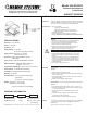
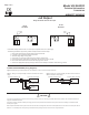
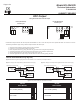
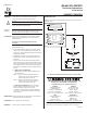
Table Of Contents
Accuracy*: ± 2% / ±3% RH
Range: 0–100% RH
Hysteresis: ± 1%
Supply Voltage: 12–40 VDC
12–35 VAC (VDC output units only)
Supply Current: VDC Units – 10 mA max.
mA Units – 20 mA max.
Enclosure: 18 Ga C. R. Steel NEMA 4 (IP-65)
or ABS Plastic
Finish: Baked on enamel–PMS2GR88B or off-white
EMC Conformance: EN 55022, 55024, 61000-3-3,
61000-4-2, 3, 4, 5, 6 & 11
Compensated Temp Range: -30°F to 130°F (-35°C to 55°C)
Environmental: 10–90%RH Non-Condensing
Termination: Unpluggable screw terminal block
Wire Size: 12 Ga max.
Load Impedance: 1.5K ohms max. at 40 VDC (mA
output units)
1K ohms min. (VDC output units)
Weight: Duct Mount: 1.0 lbs. (.45 kg)
Wall Mount: 0.5 lbs (.25 kg)
*Includes non-linearity and non-repeatability
PACKAGING OUTPUT
SPECIFICATIONS
Inspection
Requirements
Mounting
HU-224 (Duct Mount)
HU-225 (Wall Mount)
(4–20 mA 2-wire)
(0–5 VDC/0–10 VDC
field selectable)
mA
VDC
Ex: HU-224-2-mA – Duct Humidity Transducer, ± 2% RH accuracy with 4–20 mA output.
For Additional Information See HU-224/225 Data Sheet
INSTALLATION
8189 Century Boulevard • Minneapolis, MN 55317-8002 • USA
800-843-5116 • 952-556-4900 • Fax 952-556-4997
sales@mamacsys.com • www.mamacsys.com
Model HU-224/225
Technical Information
TI.224/225-08
HUMIDITY SENSOR
Inspect the package for damage. If damaged, notify the appropriate
carrier immediately. If undamaged, open the package and inspect
the device for obvious damage. Return damaged products.
Warning:
• Do not use on oxygen service, in an explosive/hazardous
environment, or with flammable/combustible media.
• Disconnect power supply before installation to prevent
electrical shock and equipment damage.
• Make all connections in accordance with the job wiring
diagram and in accordance with national and local
electrical codes. Use copper conductors only.
Caution:
• Use electrostatic discharge precautions (e.g., use of wrist
straps) during installation and wiring to prevent equipment
damage.
• Avoid locations where severe shock or vibration, excessive
moisture or corrosive fumes are present. NEMA Type 4
housings are intended for outdoor use primarily to provide
a degree of protection against wind-blown dust, rain, and
hose-directed water.
• Do not exceed ratings of the device.
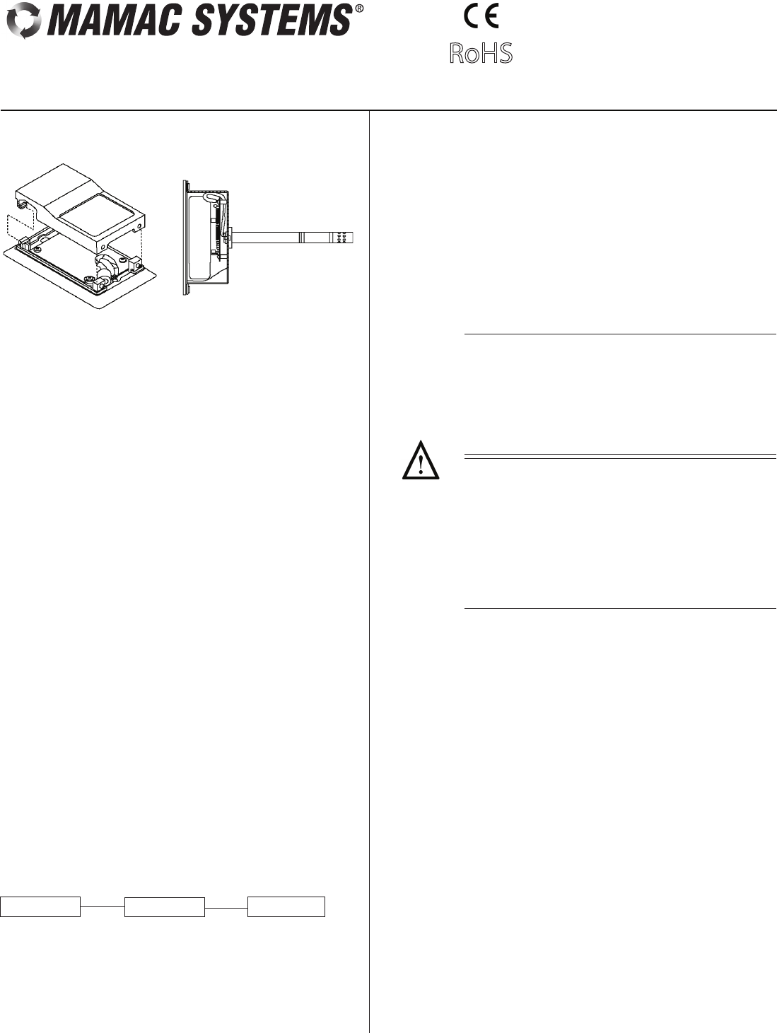
HU-224 (DUCT) – The HU-224 must be mounted as referenced by
Figure 6.
1. Drill 5/8" hole in appropriate location.
2. Mount transducer on a vertical surface with two #8 self-tapping
screws (not provided).
3. Pull wires through knockout and make necessary connections
(see wiring drawings).
4. Replace cover and tighten Philips screws.
• Tools (not provided)
- Digital Volt-ohm Meter (DVM)
- Appropriate screwdriver for mounting screws
- Appropriate drill and drill bit for mounting screws
• Appropriate accessories
• Two #8 self-tapping mounting screws (not provided)
• Training: Installer must be a qualified, experienced technician
RoHS
ACCURACY
± 2%
± 3%
ORDERING INFORMATION
HU-225 (WALL) – The HU-225 must be mounted as referenced by
Figure 6.
1. Turn both allen screws CW on bottom of unit – remove cover.
2. Select the mounting location (locate away from diffusers, lights,
or any external influences).
3. Mount transducer on a vertical surface with two screws
provided.
4. Pull wires through sub base hole and make necessary
connections (see wiring drawings).
5. Replace plastic cover and turn allen screws CCW.
HU-225
Executive Style
(Wall Mount)
HU-224
Duct Mount
Wiring
Use maximum 12 AWG wire for wiring terminals. Refer to Figures
1, 2, 3, & 4 for wiring information and Figure 5 for dip switch
designations.
(Wiring Instructions continued on Pages 2 & 3.)