Installation Manual For The Ford ACCEL Digital Fuel Injection Engine Management System Part #74030 The Mr. Gasket Performance Group Cleveland, Ohio 216.398.8300 www.mrgasket.
ACCEL/DFI Prior to starting the installation of your ACCEL DFI system, read this manual carefully!! Contents Pages Introduction 1 I) Obtaining Your Manifold 2 II) Setting Up Your Manifold 2 III) Mounting Your ACCEL ECM 4 IV) Injector Harness Installation 5 V) Main Wire Harness Routing And Connections 5 VI) Choosing Your Distributor 9 VII) Fuel Pump Mounting and Fuel Line Installation 13 VIII) Mounting The Oxygen Sensor 19 IX) Air Cleaner Assembly 20 X) Starting The Vehicle 20 XI) Optio
ACCEL/DFI INTRODUCTION CONGRATULATIONS! You have just purchased the finest engine management system available. EFI control is an exact science that ACCEL has made simple. This manual is written to assist you with the installation of your new system to your FORD application. Please read this manual carefully. Prior to starting your installation, please verify the contents of your ACCEL DFI package.
ACCEL/DFI Although this package is designed to allow you to convert a carbureted engine to fuel injection or allow you better control over your present fuel injected engine, it does not include the hydraulic portion of the installation. If you need a fuel pump, filter, fittings, etc. contact your local ACCEL EMIC center for the proper ACCEL DFI part numbers for your application. I.
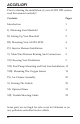
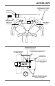
ACCEL/DFI 1-5/8 Hole thru firewall for grommet in main harness - 2 places TPS Sensor IAC Motor MAP Sensor Main Wire Harness Main Wire Harness Manifold Vacuum to Pressure Regulator Manifold Vacuum to MAP Sensor Manifold Vacuum to Automatic Transmission Modulator PCV Valve Vacuum Line Manifold Vacuum to Power Barke Booster Additional Manifold Vacuum Sources.
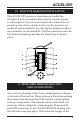
ACCEL/DFI Throttle Body IAC Gasket IAC Adapter Plate Bolt Size IAC Housing Bolt Size IAC Valve III. MOUNTING YOUR ECM The ECM comes with three (3) mounting tabs designed for a #8 sheet metal screw. It is recommended that you mount the ECM in the passenger side kick panel. If the kick panel has an air vent incorporated into it, DO NOT mount the ECM here. This unit is not waterproof and therefore needs to be mounted in a location free of moisture.
ACCEL/DFI IV. INJECTOR HARNESS INSTALLATION This ACCEL DFI system is simultaneous double fire, therefore it does not matter what injector connector goes to what injector. For your convenience the connectors are paired in sets of two, similar to the way the injectors are mounted in the manifold. Lay the injector harness so that it lays naturally on the manifold. Clip the connectors onto the fuel injectors making sure that the metal clips snap into place. 4 8 3 7 2 6 1 5 V.
ACCEL/DFI two legs through the drivers side firewall hole that you cut in step two followed by the shorter leg though the passenger side firewall hole. Continue pulling the harness legs through the firewall until the rubber grommets seat themselves in the firewall. Once the grommets have been properly seated into the firewall, each leg can be routed between the manifold and the valve covers.
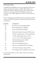
ACCEL/DFI • Oxygen (3-pin female black connector) • Injector (5-pin round white connector) • Tach pick-up (1-pin brown connector) • Fuel pump (bare lead, red wire with white stripe) • IAC (4-pin square male black connector) Connect each to the appropriate sensor using the diagram at the end of this section. If you need to lengthen the fuel pump wire to reach your fuel pump, make sure to use at least 14 gauge wire, soldering and heat shrinking the connection between the two wires.
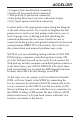
ACCEL/DFI 5 PIN Grey Connector to Main Harness 5 PIN Black Connector to Injector Harness (Male) Firewall Pink Wire to 12V Switched on Fuse Box 3 PIN Black Connector to O2 Sensor Grommet Red/White to Fuel pump Positive (+) 2 PIN Black Connector to Water Temp Sensor 3 PIN Green Connector to MAP Sensor 3 PIN Black Connector to TPS Sensor Only connect white wire to negative (–) side of ignition coil when using a non-computer controlled distributor.
ACCEL/DFI VI. CHOOSING YOUR DISTRIBUTOR NON-COMPUTER-CONTROLLED IGNITION If you are using a stand-alone magnetic pick-up distributor, points distributor, etc., the Tach pick-up (1-pin brown connector) must be used. Connect this lead to the negative side of the coil. If the brown connector must be removed, make sure not to remove the 39K ohm resistor which is located 3” away from the existing connector. NOTE: If you are using an aftermarket ignition enhancer box (i.e.
ACCEL/DFI The total advance to which you set the engine will depend upon the engine you have. Vacuum advance should be controlled with the EGR port, which is located before the throttle blades. ACCEL DFI recommends a distributor with an adjustable vacuum advance. Once the total advance is set, connect the vacuum line to the canister. Adjust the canister to maintain 20-26 degrees with a hot idle at 800 RPM.
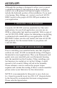
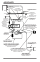
ACCEL/DFI Thick Film Module Jumper Harness to be connected between Distributor and Main Wiring Harness 4 Way Connector on Main Wiring Harness Distributor DFI 4 PIN PIP SPOUT BLANK SWITCHED GN COIL (–) GND A B C D – – – – EST (B–1) REF (A–2) Switched GN (D–7) GND (A–12) – + One Way Female Connector One Way Male Connector provided with kit COIL Instructions for assembling 1,2,3,4 or 6 Way electrical connectors Push to insert Male Terminal Seal 12-16 GA Wire Connector Push to insert Female Termin
ACCEL/DFI curve is pre-programmed into the ECM from ACCEL DFI. It has initial timing of 20 degrees BTDC and a total timing of 34 degrees BTDC in by 3000 RPM. The timing curves, as well as all other tables in the ECM, can be adjusted to better suit your engines requirements using ACCEL DFI’s calibration software “CALMAP”. NOTE: If an aftermarket ignition enhancer box is used (i.e. ACCEL 300+, MALLORY HyFire), the TFI distributor can be wired as described by the manufacturer of the enhancer box.
ACCEL/DFI VII. FUEL PUMP MOUNTING AND HIGH PRESSURE LINE INSTALLATION ACCEL DFI currently has two high pressure fuel pumps available: part number 74701, an external mount fuel pump which can support up to 450 horsepower @ 45 PSI, and part number 74702 which can support up to 840 horsepower @ 45 PSI. This fuel pump can be mounted in the fuel tank or on the frame rail. You can use part number 74710 to mount this pump onto your frame rail.
ACCEL/DFI MECHANICAL PUMP REMOVAL If your engine was carbureted, be sure to either cap off the fittings on your mechanical pump or remove the pump and cover the opening with a block off plate. HIGH PRESSURE FUEL FILTER MOUNTING Locate the high pressure fuel filter at the outlet of the high pressure fuel pump on the frame rail. It is recommended to place a filter between the fuel tank outlet and the pump inlet if the pickup tube in the tank does not have a filter.
ACCEL/DFI DUAL FUEL TANKS It is important to note that for vehicles with two fuel tanks and/or a class “A” RV, it is highly recommended that a boost pump be installed in each tank and feed though a multi-port switching valve, especially when operating in hot climates. Boost pumps used on such vehicles as a 1985 Ford F-250 5.0L EFI will work well for this type of application. The switching valve from a 1984 Ford Diesel or a 1986 Chevrolet C-10 (305 CID) will work well in dual tank applications.
ACCEL/DFI SENDING UNIT MODIFICATIONS To install a return line in your tank, remove the sender assembly from the fuel tank and drill a 5/16” hole through the top of the flange. Be sure to give yourself enough room to weld the tube into place, welding procedures are discussed later in this section. ACCEL DFI jumper line kit, part number 74731, will supply you with this line as well as other lines that you may need.
ACCEL/DFI 5/16 Fuel Return Line Must Be Added to Non-Fuel Injected Vehicles.
ACCEL/DFI IX. AIR CLEANER ASSEMBLY If you are using a stock throttle body on your application, the ACCEL POWERFILTER division of ACCEL may very well have a high performance reusable air cleaner for you. They may also have one for your custom application, contact ACCEL’s Technical support team for more information. At this point all the electrical connections should be made between the sensors, computer, and optional equipment.
ACCEL/DFI A) All electrical and mechanical connections are made securely. B) There are no fuel leaks. C) The fuel feed line is pressurized with fuel. The most common problem is the fuel pump is wired backward. On the ACCEL pumps, the positive (+) and negative (-) designations are casted in the pump adjacent to the terminals. If the ACCEL 74702 pump is wired backwards, it will run backwards. D) Ensure that the engine timing is properly set. XI.
ACCEL/DFI Communications Interface option, CALMAP (part number 74990-S with a 5ft cable, 74990-L with a 25ft cable). This software will allow you to customize the Fuel and Timing curves as well as all other parameters in the ECM. FAN CONTROL KIT (PART NUMBER 74171) This kit includes a harness with a integral relay that interfaces between the ECM and the fan. This allows you to turn on an electric fan at a given engine temperature via CALMAP. This kit does not include a fan.
ACCEL/DFI XII. TROUBLE SHOOTING GUIDE The following are some common problems we have encountered with various installations. Injectors not firing (clicking) - the vehicle will not start: • Usually due to a low battery. Voltage must be above nine (9) volts during cranking to activate the ECM. • Injector harness not connected to the main wiring harness. • Short in either pin P1-C7 or P1-C8. Check continuity to battery positive (+) and negative (-) wires with an OHM meter.
The Mr. Gasket Performance Group Cleveland, Ohio 216.398.8300 www.mrgasket.com Printed in U.S.A.