
User guide

www.accel-dfi.com ACCEL/DFI TECHNICAL SUPPORT 248.380.27808
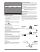
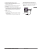
There are three different large cap HEI distributors. To identify which
of the following diagrams fit your specific application, remove the
distributor cap and rotor and locate the ignition module at the base
of the distributor. Count the number of terminals on both ends of the
module and follow the corresponding diagram. GM used 4, 5, and
7-pin modules in these distributors.
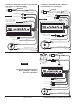
NOTE: Some 5-pin modules may experience a hesitation or stall on
deceleration. If this occurs, contact the ACCEL/DFI Technical Service
Department for the required bolt-in diode to correct the problem.
4-Pin Module 5-Pin Module
®
PART No. 6852
R
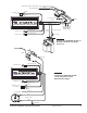
DARK BLUE
RED/WHITE
NOT USED
YELLOW
TO TACHOMETER
BLACK (LARGE 14 GA)
TO BATTERY NEG (
-
)
RED (LARGE 14 GA)
TO BATTERY POS (+)
BLACK (TO C+)
RED (TO B+)
PURPLE
GREEN
WHITE
GREEN
TO ENGINE
GROUND
WHITE JUMPER
KEY CONNECTOR
HEAVY RED OR PINK WIRE FROM CAR
WIRING HARNESS
GREEN
PURPLE
PART OF MALLORY HEI KIT
P/N 29008 (NOT INCLUDED)
PART OF MALLORY HEI KIT
P/N 29008 (NOT INCLUDED)
SHIELD DRAIN
TO TACH
BLACK (LARGE 14 GA)
TO BATTERY NEG (–)
RED (LARGE 14 GA)
TO BATTERY POS (+)
®
PART No. 6852
R
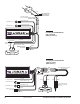
YELLOW
TO TACHOMETER
BLACK (TO C+)
RED (TO B+)
TO ENGINE
GROUND
NOT USED
RED/WHITE
DARK BLUE
RED JUMPER
WHITE JUMPER
HEAVY PINK OR RED FROM
VEHICLE WIRE HARNESS
GREEN
PURPLE
PART OF MALLORY HEI KIT
P/N 29008 (NOT INCLUDED)
PART OF MALLORY
HEI KIT P/N 29008
(NOT INCLUDED)
PART OF MALLORY
HEI KIT P/N 29008
(NOT INCLUDED)
SHIELD DRAIN
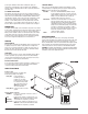
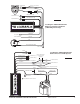
Installing the ACCEL/DFI 6A with an HEI
4-Pin Module (Magnetic Pickup Trigger)
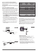
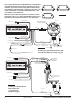
Installing the ACCEL/DFI 6A
with an HEI 5-Pin
or 7-Pin Module
(Amplifier Trigger)
7-Pin Module
FIGURE 13
FIGURE 14
FIGURE 15
HHYYFFIIRREE 66AA
AACCCCEELL//DDFFII 66AA
ELECTRONIC IGNITION CONTROL MODULE
PART No. 75606
AACCCCEELL//DDFFII 66AA
ELECTRONIC IGNITION CONTROL MODULE
PART No. 75606
SHIELDED CABLE
SHIELDED CABLE