
User Manual


ROBOT . HEAD to TOE
Product User’s Manual – HAT-MDD10
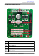
F
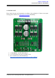
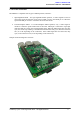
Raspberry Pie Connector
G
Power LED Indicator
H
PWM1 input (GPIO12)
I
DIR1 input (GPIO26)
J
PWM2 input (GPIO13)
K
DIR2 input (GPIO24)
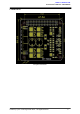
1. Terminal Block – Connect to motor and power source.
Pin Name
Description
1
M1A
Connect to motor1 terminal A
2
M1B
Connect to motor1 terminal B
3
VM
Positive Supply (6V to 24V
*1
)
4
GND
Negative Supply
5
M2A
Connect to motor2 terminal A
6
M2B
Connect to motor2 terminal B
*1: Absolute Maximum
2. M1A/M2A LED Indicator – Turns on when the output A is high and output B is low.
Indicates the current flows from output A to B.
3. M1B/M2B LED Indicator – Turns on when the output A is low and output B is high.
Indicates the current flows from output B to A.
4. M1A/M2A Test Switch – When this button is pressed, current flows from output A to B
and motor will turn CW (or CCW depending on the connection).
5. M1B/M2B Test Switch – When this button is pressed, current flows from output B to A
and motor will turn CCW (or CW depending on the connection).
6. Input
.
Pin Name
Description
1
GND
Logic ground.
2
**PWM1 (GPIO12)
PWM input for motor 1 speed control
3
DIR1 (GPIO26)
Direction control for motor 1.
Created by Cytron Technologies Sdn. Bhd. – All Rights Reserved 6