Content LED Puzzle Game..............................................................4 Assembly..............................................................5 Game manual......................................................11 Technical description...........................................
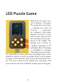
LED Puzzle Game Build your own game console featuring a cult game! The design does not require a soldering iron since all necessary connections are equipped with plugs. Immerse yourself 30 years back in time when the first electronic games were introduced on the Market. The playing area is shown on a display consisting of 120 individual LEDs. Everything is controlled by a modern ATmega168 microcontroller. Use six buttons to move and rotate the falling blocks, which should be stacked as exactly as possible.
Technical data: Microcontroller ATmega168, 16 KB Flash, clock rate 8 MHz 120 red SMD LEDs, multiplexed Sound output via piezo electroacoustic transducer Operating voltage 4.5 V (3 AA batteries required) Current consumption: 5 mA to 15 mA, depending on display content Power consumption in sleep mode: 20 μA Operating time with one set of batteries: approx.
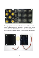
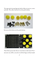
The appropriate connectors are located at the cable ends of the battery compartment and the speaker. The dark filter disc is mounted over the LED field to increase the contrast. The protective film on both sides must be removed before installation.
The appropriate mounting material includes six spacers, screws and nuts. The yellow buttons fit on the push buttons. First press the buttons on the push buttons. Then fit the spacers into the six screw holes on the board.
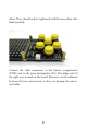
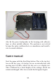
effort. They should only be tightened with flat nose pliers after final assembly. Connect the cable connectors to the battery compartment (PWR) and to the piezo loudspeaker (LS). The plugs only fit the right way around on the board. However, avoid confusion between the two connections, as this can damage the microcontroller.
Now you can already insert batteries and carry out a first test run without the housing. Install thereafter the circuit board with the spacers in the housing. Four of the six screws simultaneously hold the filter disc, which is previously placed on the housing from the outside so that the four mounting holes fit over those of the housing. Before tightening all screws, check that all parts are seated correctly.
Stick the battery compartment with double-sided adhesive tape on the back of the board in the area of the LED display. The adhesive tape is also an important insulation between the circuit board and conductive parts of the battery compartment. First remove only the lower protective foil of the enclosed double-sided adhesive tape and then stick the adhesive tape centrally on the back of the board in the area of the LEDs.
Also fix the piezo loudspeaker in the housing with adhesive tape, or other suitable adhesive. The position is not critical because the entire cardboard acts as a membrane and contributes to sound radiation. Game manual Start the game with the Start/Stop button. This is the top button on the key cross. At startup you see an introduction with moving rows of LEDs, which can also serve as a display test. This is followed by a brief display of the settings, which can remain unchanged.
Blocks of different shapes fall down from above at random. Use the key cross to move the position to the left or right. You can also stop the fall with the top button and accelerate it with the bottom button. Use the right buttons to rotate the blocks to the left or right. The aim of the game is to stack the blocks so that no gaps are left. Start/Stop Left Rotate right Right Rotate left Down Whenever a row is completely filled, it is deleted. This creates space for more blocks.
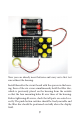
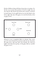
One blocked aligned to fit The blocks can be rotated during the fall. The following picture shows an L-shaped block in its initial position, turned 90 degrees to the left and turned 180 degrees. During a rotation, the left column is always retained as the current position.
Rotating a block If you want to know how many positions a block should be moved to the left or right, you can press the corresponding button in quick succession and do not have to wait for the movement. The commands are stored and executed together. Likewise, a rotation of 90 degrees or a double rotation of 180 degrees in total can be carried out simultaneously with shifts.
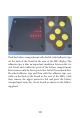
In fact, it is not easy to operate all buttons at the same time. At the beginning you may not use the rotation and only change the position of the falling blocks. However, there are more frequent situations in which a gap becomes unavoidable. A typical game situation The picture shows a typical game situation in which the next move counts. The playing field is almost half full because numerous gaps have formed in the lower area.
just fell. The chance in this case is to rotate it 90 degrees and move it three positions to the left. Then the upper row is complete and will be deleted. After that, with a bit of luck, you still have the opportunity to fill in the gaps further down and, ideally, to slowly reduce the field again. You can hear sounds during the game, but they can also be turned off. Each landed block produces a sound.
In addition, at the end of a game the scored points are displayed, whereby each landed block brings between two and four points according to the number of LEDs. Each digit is represented by a vertical column, which contains a gap above position 5 for better legibility. In the example, 167 points were achieved, which is already a very good result. After a total of five matches, the overall result is displayed, i.e. the sum of all five individual results.
Block level 5, speed 3, sound on As long as the level display is visible, you can change the settings. Use the left and right keys to change the speed level. Use the Start/Stop and down keys to set the block level. The two right buttons (rotation) switch the sound on or off.
the settings made. The set speed level determines the time in which a block falls down one line. In the first step with one second per line you have up to twelve seconds to set the position and direction of a block. This setting is convenient when you are just starting to play. Once you know the game better, you can increase the speed. Speed 1: 1.0 seconds Speed 2: 0.5 seconds Speed 3: 0.3 seconds Speed 4: 0.2 seconds Speed 5: 0.
All blocks in level 5 If you want to start very simply, you can play in block level 1 with only one block of three. In the second level you can already play with three simple blocks.
Block level 1 (up) and 2 (down) Three more blocks are added in level 3.
Six blocks in level 3 In level 4 you only have four different blocks, but it’s the selection of the most difficult blocks that usually have to be rotated in order to be optimally stacked. Level 4 is therefore even more difficult than level 5, where you always get simple blocks to fill gaps. In level 4, the simultaneous rotation and position change is practiced particularly effectively, whereby it is useful to slowly increase the speed.
Difficult blocks in level 4 If you have worked your way through all levels, you can play at your own speed at the end of block level 5. A first stage goal could be to reach 100 points per game. Maybe you’ll end up playing real tournaments with peers. Each player then plays five games, and the total score of all five games is recorded. By the way, the scoreboard max is 9999, but nobody has achieved that yet.
Technical description The core of the game is an ATmega168 controller clocked at 8 MHz by its internal RC oscillator. A matrix with 120 LEDs is arranged in ten rows with twelve LEDs each. The microcontroller controls the rows in a multiplex process. The anodes are controlled directly via ports, the cathodes via the two shift registers HC4094. The controller can put itself in power-down mode. All LEDs are switched off, so that the power consumption drops to 20 μA Therefore no main switch is required.
You will find some unused connections on the board. They are partly needed for production and are also useful for your own projects. The six-pin ISP connection allows you to reprogram the controller and develop your own projects. However, only do this if you already have experience with microcontrollers, because a fault could damage the system.
Imprint Dear Customers, This product has been manufactured in accordance with the applicable European directives and therefore bears the CE mark. The intended use is described in the enclosed instructions. For any other use or modification of the product, you are responsible to comply with applicable rules. Therefore, install the circuits exactly as described in the instructions. The product may only be distributed along with this manual.