
Data Sheet

Smart Machine Smart Decision
SIM800F_Hardware Design_V1.00 48 2015-07-31
4.20.2 Bluetooth Antenna Interface
For Bluetooth antenna, it is recommended to reserve the matching circuit as following:
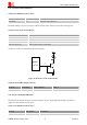
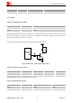
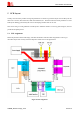
Figure 44: Bluetooth antenna matching circuit
R201, C201, C202 are the matching circuit, the values depend on antenna debug result. Normally R201 is 0,
C201 and C202 are not mounted.
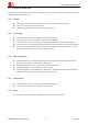
There are some suggestions for placing components and RF trace for GSM_ANT/BT_ANT:
The RF connector is used for conducted test, so keep it as close to pin GSM_ANT as possible
Antenna matching circuit should be close to the antenna
Keep the RF traces impedance as 50
The RF traces should be kept far away from the high frequency signals and strong interference
source