
Data Sheet

Smart Machine Smart Decision
SIM800F_Hardware Design_V1.00 47 2015-07-31
4.20.1 GSM Antenna Interface
SIM800F provides a GSM antenna named GSM_ANT, customer could use 50 microstrip line or stripline
antenna connect to the module.
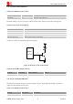
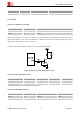
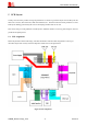
It is recommended to reserve the matching circuit as following:
Module
GND
(Pin61)
R101
GSM_ANT
C101
C102
GND
(Pin59)
GSM
Antenna
Figure 42: GSM antenna matching circuit
R101,C101,C102 are the matching circuit, the value should be defined by the antenna design. Normally R101 is
0, C101 and C102 are not mounted.
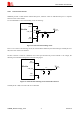
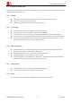
The RF connector is used for conduction test. If the space between RF pin and antenna is not enough, the
matching circuit should be designed as in the following figure:
Module
R101
GSM_ANT
C101
C102
GND
(Pin61)
GND
(Pin59)
GSM
Antenna
Figure 43: GSM antenna matching circuit without RF connector
Normally R101 is 0; C101 and C102 are not mounted.