
Data Sheet

Smart Machine Smart Decision
SIM800F_Hardware Design_V1.00 45 2015-07-31
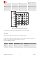
Table 32: STATUS multiplex function
Pin name Pin number Mode 0(default) Mode 1
STATUS 66 STATUS GPIO
4.17 PWM
Table 33: Pin definition of the PWM
PWM output frequency varies from 0 to 2KHz.Two 7-bit unsigned binary parameters are used for the output
period and for the duty cycle. The AT command “AT + SPWM” is used to set the output period and duty cycle of
the PWM. For details, please refer to document
[1]
.
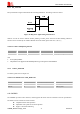
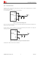
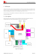
A typical circuit of the PWM drives buzzer is shown in the following figure:
Figure 40: Reference circuit of PWM drive buzzer
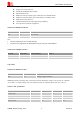
Table 34: PWM output characteristics
Parameter Min Typ Max Unit
Working voltage 2.5 2.8 2.9 V
Working current 4 16 mA
Note: PWM pin must keep low when module is in the boot process.
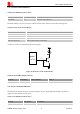
Table 35: PWM multiplex function
Pin name Pin number Description
PWM1 35 PWM1
PWM2 36 PWM2
Pin name Pin number Mode 0(default) Mode 1
PWM1 35 PWM1 GPIO
PWM2 36 PWM2 GPIO