
Data Sheet

Smart Machine Smart Decision
SIM800F_Hardware Design_V1.00 41 2015-07-31
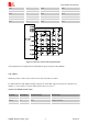
KBR1 43 GPIO KBR1
KBR0 44 GPIO KBR0
KBC4 47 GPIO KBC4
KBC3 48 GPIO KBC3
KBC2 49 GPIO KBC2
KBC1 50 GPIO KBC1
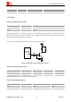
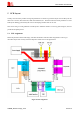
Figure 37: Reference circuit of the keypad interface
Note: keypad function is not supported in the standard firmware. If you need, please contact SIMCom..
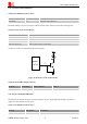
4.12 GPIO
SIM800F provides 3 GPIO, which could be used as RF_SYNC/JD and UART2.
For GPIO function, both output and input voltage level of the GPIO can be set by the AT command “AT+
SGPIO” or “AT+CGPIO”. For more details, please refer to document
[1]
.
Table 21: Pin definition of the GPIO
Pin Name Pin Number Default Function Default State
GPIO10 51 GPIO Output, Pull down
GPIO11 67 GPIO Output, Pull down
GPIO12 68 GPIO Output, Pull down