
Data Sheet

Smart Machine Smart Decision
SIM800F_Hardware Design_V1.00 36 2015-07-31
4.8.3 Audio Electronic Characteristics
Table 13: Microphone Input Characteristics
Parameter Min Typ Max Unit
Mic biasing voltage - 1.9 2.2 V
Working Current - - 2.0 mA
Input impedance(differential) 13 20 27 K
Idle channel noise - - -67 dBm0
Input level:-40dBm0 29 - - dB
SINAD
Input level:0dBm0 - 69 - dB
Table 14: Audio Output Characteristics
parameter Conditions Min Typ Max Unit
Normal output R
L
=32 receiver - 15 90 mW
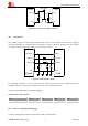
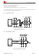
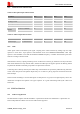
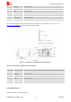
4.8.4 TDD
Audio signal could be interfered by RF signal. Coupling noise could be filtered by adding 33pF and 10pF
capacitor to audio lines. 33pF capacitor could eliminate noise from GSM850/EGSM900MHz, while 10pF
capacitor could eliminate noise from DCS1800/PCS1900Mhz frequency. Customer should develop this filter
solution according to field test result.
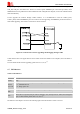
GSM antenna is the key coupling interfering source of TDD noise. Thereat, pay attention to the layout of audio
lines which should be far away from RF cable, antenna and VBAT pin. The bypass capacitor for filtering should
be placed near module and another group needs to be placed near connector.
Conducting noise is mainly caused by the VBAT drop. If the audio PA was powered by VBAT directly, then there
will be some cheep noise from speaker output easily. So it is better to put big capacitors and ferrite beads near
audio PA input.
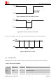
TDD noise has something to do with GND signal. If GND plane is not good, lots of high-frequency noises will
interference microphone and speaker over bypass capacitor. So a good GND during PCB layout could avoid
TDD noise.
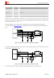
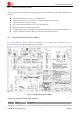
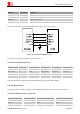
4.9 SIM Card Interface
4.9.1 SIM Card Application
The SIM interface complies with the GSM Phase 1 specification and the new GSM Phase 2+ specification for
FAST 64 kbps SIM card. Both 1.8V and 3.0V SIM card are supported.