
Data Sheet

Smart Machine Smart Decision
SIM800F_Hardware Design_V1.00 29 2015-07-31
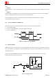
4.6 Serial Port and USB Interface
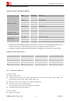
Table 8: Serial port and USB pin definition
Note:
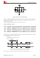
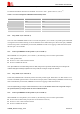
1. Hardware flow control is disabled by default. The AT command “AT+IFC=2,2” can enable hardware flow control .The AT
command “AT+IFC=0,0”can disable hardware flow control. For more details, please refer to document
[1]
.
2. Pin 68 &51 are configured as GPIO by default. AT command “AT+CMNRP=1” can set them to be serial port UART2.
Table 9: Serial port characteristics
Symbol Min Max Unit
V
IL
-0.3 0.7 V
V
IH
2.1 3.1 V
V
OL
- 0.4 V
V
OH
2.4 - V
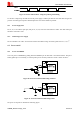
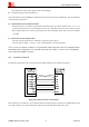
4.6.1 Function of Serial Port
Serial port UART1:
Support modem device
Contain data lines UART1_TXD, UART1_RXD,hardware flow control lines UART1_RTS, UART1_CTS
and status lines UART1_DTR, UART1_DCD, UART1_RI
Serial port can be used for GPRS service and AT communication
Serial port supports the following baud rates
1200, 2400, 4800, 9600, 19200, 38400, 57600 and 115200bps
The default setting is auto baud detection
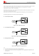
Serial port UART2:
Support AT command
Name Pin number Function
UART1_DTR 3 Data terminal ready
UART1_RI 4 Ring indicator
UART1_DCD 5 Data carrier detect
UART1_CTS 7 Clear to send
UART1_RTS 8 Request to send
UART1_TXD 9 Transmit data
Serial port UART1
UART1_RXD 10 Receive data
GPIO12 68 Compatible with UART2_TXD, Transmit data Serial port UART2
(enabled by command)
GPIO10 51 Compatible with UART2_RXD, Receive data
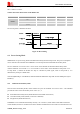
USB_VBUS 24 USB power supply
USB_DP 27 USB data line plus
USB interface
USB_DN 28 USB data line minus