
Data Sheet

Smart Machine Smart Decision
SIM800F_Hardware Design_V1.00 26 2015-07-31
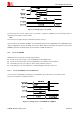
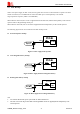
RESET pin is pulled up to 2.8V internally, so the users could set the GPIO as an open-drain output pin when use
MCU’s GPIO to control it.
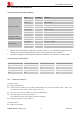
Table 6: Electronic characteristic of the RESET Pin
Pin name Symbol Min Typ Max Unit
V
IH
2.7 - 2.9 V
V
IL
- - 0.6 V
RESET
T
pull down
105 - mS
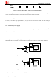
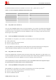
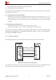
The reset sequence is illustrated as below:
Figure 16: Reset timing
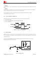
4.4 Power Saving Mode
SIM800F has two power saving modes: minimum functionality mode and sleep mode. The power consumption
can be reduced to the minimum when SIM800F is in both sleep mode and minimum functionality mode.
The AT command “AT+CFUN=<fun>” can be used to set the module into minimum functionality mode.
And the command “AT+CSCLK=1” or “AT+CSCLK=2” can be used to set the module into sleep mode 1 or 2.
In sleep mode 1, whether the module can sleep is controlled by DTR signal, while in sleep mode 2, it is
determined by serial port’s RXD status.
Note: The default setting is “AT+CSCLK=0”, which do not allow the module enter sleep mode. For more details please refer to
document
[1].
4.4.1 Minimum Functionality Mode
There are three functionality modes, which could be set by the AT command “AT+CFUN=<fun>”. The command
provides the choice of the functionality levels <fun>=0, 1, 4.
0: minimum functionality mode (disable RF function and SIM card function)
1: full functionality mode (default, no function is disabled)
4: flight mode (disable RF function)
If SIM800F is set to minimum functionality mode by “AT+CFUN=0”, the RF function and SIM card function
will be disabled, and all AT commands correlative with RF and SIM card functions will be invalid. But the serial