
Data Sheet

Smart Machine Smart Decision
SIM800F_Hardware Design_V1.00 22 2015-07-31
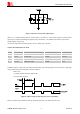
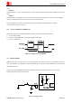
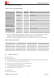
Figure 9: The low limit of VBAT voltage drop during transmitting
To decrease voltage drop, the PCB traces from power supply to VBAT pins must be wide and short enough. The
power IC and the bypass capacitor should be placed as close to the module as possible.
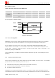
4.1.1 Power Supply Pins
Pin 55, 56, 57 are VBAT input pins, and pin 62, 63, 64, 65 are the main GND for VBAT. The other GND pins
should be connected as well.
4.1.2 Monitoring Power Supply
The AT command “AT+CBC” can be used to monitor the VBAT voltage. For detail, please refer to
document
[1]
.
4.2 Power on/off
4.2.1 Power on SIM800F
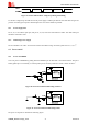
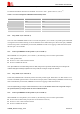
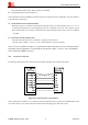
Users can power on SIM800F by pulling down the PWRKEY pin for more than 1 second then release. This pin is
already pulled up to 3V internally, so external pull up is not necessary. Reference circuit is shown as below:
Figure 10: Powered on/down module using transistor
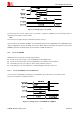
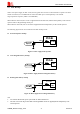
Figure 11: Powered on/down module using button
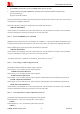
The power on sequence is illustrated as following figure: