
Data Sheet

Smart Machine Smart Decision
SIM800F_Hardware Design_V1.00 21 2015-07-31
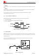
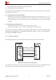
Figure 7: Reference circuit of the VBAT input
Where C
A
is a 100uF tantalum capacitor with low ESR; C
B
could be a 1~10uF ceramic capacitor; 33PF and 10PF
capacitors are used for eliminating the high frequency interference; 5.1V/500mW zener diode can protect the
module against voltage surge.
All of these components should be placed as close to VBAT pins as possible.
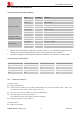
Table 5: Recommended zener diode
Vendor Part number Power(watts) Packages
1 On semi MMSZ5231BT1G 500mW SOD123
2 Prisemi PZ3D4V2H 500mW SOD323
3 Vishay MMSZ4689-V 500mW SOD123
4 Crownpo CDZ55C5V1SM 500mW 0805
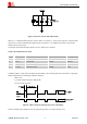
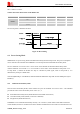
In addition, VBAT voltage will drop during the transmitting. The following figure shows the VBAT voltage drop
during maximum power transmitting under the condition:
VBAT=4.0V
C
A
=100µF tantalum capacitor (ESR=0.7)
C
B
=1µF ceramic capacitor
Figure 8: VBAT voltage drop during max power transmitting
However, hardware may shutdown once the voltage drops below 3.0V, which must be avoid.