
Data Sheet

Smart Machine Smart Decision
SIM800F_Hardware Design_V1.00 20 2015-07-31
4 Application Interface
4.1 Power Supply
The power supply of SIM800F ranges from 3.4V to 4.4V, and 4.0V is recommended. It must be able to provide
sufficient current up to 2A for the high-power transmitting.
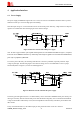
If the DC input voltage is +5V and customers do not care about the power efficiency, a high-current low-dropout
regulator is recommended. The following figure is the reference design.
Figure 5: Reference circuit of the LDO power supply
Note: To ensure a proper behavior of the regulator under light load, an extra minimum load (R103 in Figure 5) is required,
because the current SIM800F consumed is very small in sleep mode and power off mode. For more details about minimum load,
please refer to specification of MIC29302.
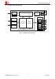
To increase power efficiency, the switching mode DC-DC converter is preferable, especially when DC input
voltage is quite high. The following figure is the reference design, and it is recommended to reserve a proper
ferrite bead (FB101 in Figure 6) in series for EMI suppression.
Figure 6: Reference circuit of the DC-DC power supply
For battery-powered application, the 3.7V lithium battery can be connected to SIM800F VBAT pins directly, but
other types of battery must be used carefully, since their maximum voltage may rise over the absolute maximum
voltage of the module. When battery is used, the total impedance between battery and VBAT pins should be less
than 150
m.
In any case mentioned above, at the VBAT input pin side, please take below circuit as a reference: