
Datasheet


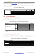


Table Of Contents
- Product Overview
- 1 ESP32-S3 Series Comparison
- 2 Pin Definition
- 3 Functional Description
- 3.1 CPU and Memory
- 3.2 RTC and Low-Power Management
- 3.3 Analog Peripherals
- 3.4 System Components
- 3.5 Digital Peripherals
- 3.5.1 IO MUX and GPIO Matrix
- 3.5.2 Serial Peripheral Interface (SPI)
- 3.5.3 LCD Interface
- 3.5.4 Camera Interface
- 3.5.5 UART Controller
- 3.5.6 I2C Interface
- 3.5.7 I2S Interface
- 3.5.8 Remote Control Peripheral
- 3.5.9 Pulse Count Controller
- 3.5.10 LED PWM Controller
- 3.5.11 USB 2.0 OTG Full-Speed Interface
- 3.5.12 USB Serial/JTAG Controller
- 3.5.13 Motor Control PWM (MCPWM)
- 3.5.14 SD/MMC Host Controller
- 3.5.15
- 3.6 Radio and Wi-Fi
- 3.7 Bluetooth LE
- 3.8 Timers and Watchdogs
- 3.9 Cryptography/Security Components
- 3.10 Peripheral Pin Configurations
- 4 Electrical Characteristics
- 5 Package Information
- 6 Related Documentation and Resources
- Revision History

4 Electrical Characteristics
ESP-IDF provides couple of calibration methods for ADC. Results after calibration using hardware + software
calibration are shown in Table 19. For higher accuracy, users may apply other calibration methods provided in
ESP-IDF, or implement their own.
Table 19: ADC Calibration Results
Parameter Description Min Max Unit
Total error
ATTEN0, effective measurement range of 0 ~ 950 -5 5 mV
ATTEN1, effective measurement range of 0 ~ 1250 -6 6 mV
ATTEN2, effective measurement range of 0 ~ 1750 -10 10 mV
ATTEN3, effective measurement range of 0 ~ 3100 -50 50 mV
4.6 Current Consumption
4.6.1 RF Current Consumption in Active Mode
The current consumption measurements are taken with a 3.3 V supply at 25 °C of ambient temperature at the RF
port. All transmitters’ measurements are based on a 100% duty cycle.
Table 20: WiFi Current Consumption Depending on RF Modes
Work Mode
1
Description Peak (mA)
Active (RF working)
TX
802.11b, 1 Mbps, @21 dBm 340
802.11g, 54 Mbps, @19 dBm 291
802.11n, HT20, MCS7, @18.5 dBm 283
802.11n, HT40, MCS7, @18 dBm 286
RX
802.11b/g/n, HT20 88
802.11n, HT40 91
1
The CPU work mode: Single core runs 32-bit data access instructions at 80 MHz, the other core is in
idle state.
4.6.2 Current Consumption in Other Modes
The measurements below are applicable to ESP32-S3 and ESP32-S3FH8. Since ESP32-S3R2, ESP32-S3R8,
ESP32-S3R8V, and ESP32-S3FN4R2 are embedded with PSRAM, their current consumption might be
higher.
Table 21: Current Consumption in LowPower Modes
Work mode Description Typ (µA)
Light-sleep VDD_SPI and Wi-Fi are powered down, and all GPIOs are high-impedance. 240
1
Deep-sleep
RTC memory and RTC peripherals are powered on. 8
RTC memory is powered on. RTC peripherals are powered off. 7
Power off CHIP_PU is set to low level. The chip is powered off. 1
1
In Light-sleep mode, all related SPI pins are pulled up. For chips embedded with PSRAM, please add
corresponding PSRAM consumption values, e.g., 140 µA for 8 MB 8-line PSRAM (3.3 V), 200 µA for 8
MB 8-line PSRAM (1.8 V) and 40 µA for 2 MB 4-line PSRAM (3.3 V).
Espressif Systems 53
Submit Documentation Feedback
ESP32-S3 Series Datasheet v1.2