
Datasheet

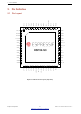


Table Of Contents
- Product Overview
- 1 ESP32-S3 Series Comparison
- 2 Pin Definition
- 3 Functional Description
- 3.1 CPU and Memory
- 3.2 RTC and Low-Power Management
- 3.3 Analog Peripherals
- 3.4 System Components
- 3.5 Digital Peripherals
- 3.5.1 IO MUX and GPIO Matrix
- 3.5.2 Serial Peripheral Interface (SPI)
- 3.5.3 LCD Interface
- 3.5.4 Camera Interface
- 3.5.5 UART Controller
- 3.5.6 I2C Interface
- 3.5.7 I2S Interface
- 3.5.8 Remote Control Peripheral
- 3.5.9 Pulse Count Controller
- 3.5.10 LED PWM Controller
- 3.5.11 USB 2.0 OTG Full-Speed Interface
- 3.5.12 USB Serial/JTAG Controller
- 3.5.13 Motor Control PWM (MCPWM)
- 3.5.14 SD/MMC Host Controller
- 3.5.15
- 3.6 Radio and Wi-Fi
- 3.7 Bluetooth LE
- 3.8 Timers and Watchdogs
- 3.9 Cryptography/Security Components
- 3.10 Peripheral Pin Configurations
- 4 Electrical Characteristics
- 5 Package Information
- 6 Related Documentation and Resources
- Revision History

2 Pin Definition
Type
Each digital function (Fn, n=0~4) is associated with a “Type”. The description of “Type” is as follows:
• O: Output only.
• O/T: The signal can be output or high-impedance.
• I/O/T: The signal can be input, output, and high-impedance.
• I1: Input only. If the pin is assigned a function other than Fn, the input signal of Fn is always “1”.
• I1/O/T: The signal can be input, output, and high-impedance. If Fn is not selected, the input signal of Fn is
always “1”.
• I0/O/T: The signal can be input, output, and high-impedance. If Fn is not selected, the input signal of Fn is
always “0”.
At Reset/After Reset
The default configuration of each pin at reset and after reset:
• IE0 - input disabled
• IE1 - input enabled
• IE1, WPD1 - input enabled, internal weak pull-down resistor enabled
• IE1, WPU1 - input enabled, internal weak pull-up resistor enabled
• IE1, or IE1&WPU1 - When the value of eFuse bit EFUSE_DIS_PAD_JTAG is
1, the MTCK pin floats after chip reset (IE1)
0, the MTCK pin connects to internal weak pull-up resistor after chip reset (IE1&WPU1)
Notes
• R - These pins have RTC or analog functions.
Drive Strength
• The default drive strength of GPIO19 ~ 20 is 2’d3 (~40 mA).
• The default drive strength of other pins is 2’d2 (~20 mA).
2.6 PintoPin Mapping Between Chip and SiP Flash/PSRAM
Table 6 lists the pin-to-pin mapping between the chip and the SiP flash/PSRAM. The chip pins listed here are not
recommended for other usage. For the data port connection between ESP32-S3 and external flash please refer
to Section 3.5.2.
Table 6: PintoPin Mapping Between Chip and SiP Flash/PSRAM
ESP32S3FN8 (8 MB) / ESP32S3FH4R2 (4 MB) SiP Flash (Quad SPI)
SPICLK CLK
SPICS0 CS#
SPID DI
SPIQ DO
SPIWP WP#
SPIHD HOLD#
Espressif Systems 19
Submit Documentation Feedback
ESP32-S3 Series Datasheet v1.2