
Datasheet

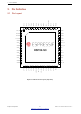


Table Of Contents
- Product Overview
- 1 ESP32-S3 Series Comparison
- 2 Pin Definition
- 3 Functional Description
- 3.1 CPU and Memory
- 3.2 RTC and Low-Power Management
- 3.3 Analog Peripherals
- 3.4 System Components
- 3.5 Digital Peripherals
- 3.5.1 IO MUX and GPIO Matrix
- 3.5.2 Serial Peripheral Interface (SPI)
- 3.5.3 LCD Interface
- 3.5.4 Camera Interface
- 3.5.5 UART Controller
- 3.5.6 I2C Interface
- 3.5.7 I2S Interface
- 3.5.8 Remote Control Peripheral
- 3.5.9 Pulse Count Controller
- 3.5.10 LED PWM Controller
- 3.5.11 USB 2.0 OTG Full-Speed Interface
- 3.5.12 USB Serial/JTAG Controller
- 3.5.13 Motor Control PWM (MCPWM)
- 3.5.14 SD/MMC Host Controller
- 3.5.15
- 3.6 Radio and Wi-Fi
- 3.7 Bluetooth LE
- 3.8 Timers and Watchdogs
- 3.9 Cryptography/Security Components
- 3.10 Peripheral Pin Configurations
- 4 Electrical Characteristics
- 5 Package Information
- 6 Related Documentation and Resources
- Revision History

2 Pin Definition
2.3 Pin Name Description
The explanation of each pin name is briefly described below.
Table 3: Pin Name Description
Pin Name Description
GPIOx
General-purpose input and output (x is GPIO number). GPIO pins can
be assigned various functions, including digital and analog functions. For
more information on digital functions, please refer to Table 5.
SPIx
SiP flash/PSRAM and external flash/RAM interface (x is CLK, CS0, CS1,
D, Q, WP, HD, IO4~7 or DQS).
XTAL_32K_P/N
32 KHz external clock input/output (connecting to ESP32-S3’s oscillator).
P/N means differential clock positive/negative.
XTAL_P/N
External clock input/output (connecting to ESP32-S3’s oscillator). P/N
means differential clock positive/negative.
U0RXD/U0TXD UART0 receive/transmit signals.
MTCK/MTDO/MTDI/MTMS JTAG interface signals.
LNA_IN Low-Noise Amplifier (RF LNA) input/output signals.
CHIP_PU Chip power up pin.
GND External ground connection.
VDDA Power supply for analog domain.
VDD3P3_RTC Power supply for RTC digital domain.
VDD3P3_CPU Power supply for digital domain.
VDD_SPI Power supply for SPI IOs.
2.4 Function Name Description
The explanation of each function name is briefly described below.
Table 4: Function Name Description
Function Name Description
RTC_GPIOx RTC domain GPIO function for low power management.
TOUCHx Analog function for touch sensing.
ADCx_CHy Analog to digital conversion channel (x is ADC number, y is channel number).
SUBSPIx
Sub-SPI0/1 bus, differing from SPIx bus (x is CLK, CS0, CS1, D, Q, WP or HD),
used for different voltage level of flash and PSRAM
FSPIx 8-line Fast-SPI2 bus function (x is CLK, CS0, CS1, D, Q, WP, HD, IO4~7 or DQS)
SPIx SPI0/1 bus function (x is CLK, CS0, CS1, D, Q, WP, HD, IO4~7 or DQS)
UxRTS/UxCTS UARTx hardware flow control signals (x is UART number).
U1RXD/U1TXD UART1 receive/transmit signals.
CLK_OUTx Clock output for debug (x is clock number).
USB_D-/USB_D+
USB OTG and USB Serial/JTAG function. USB signal is a differential signal
transmitted over a pair of D+ and D- wires.
SPICLK_N/P_DIFF Serial peripheral interface differential clock negative/positive.
Espressif Systems 16
Submit Documentation Feedback
ESP32-S3 Series Datasheet v1.2