
Datasheet

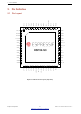


Table Of Contents
- Product Overview
- 1 ESP32-S3 Series Comparison
- 2 Pin Definition
- 3 Functional Description
- 3.1 CPU and Memory
- 3.2 RTC and Low-Power Management
- 3.3 Analog Peripherals
- 3.4 System Components
- 3.5 Digital Peripherals
- 3.5.1 IO MUX and GPIO Matrix
- 3.5.2 Serial Peripheral Interface (SPI)
- 3.5.3 LCD Interface
- 3.5.4 Camera Interface
- 3.5.5 UART Controller
- 3.5.6 I2C Interface
- 3.5.7 I2S Interface
- 3.5.8 Remote Control Peripheral
- 3.5.9 Pulse Count Controller
- 3.5.10 LED PWM Controller
- 3.5.11 USB 2.0 OTG Full-Speed Interface
- 3.5.12 USB Serial/JTAG Controller
- 3.5.13 Motor Control PWM (MCPWM)
- 3.5.14 SD/MMC Host Controller
- 3.5.15
- 3.6 Radio and Wi-Fi
- 3.7 Bluetooth LE
- 3.8 Timers and Watchdogs
- 3.9 Cryptography/Security Components
- 3.10 Peripheral Pin Configurations
- 4 Electrical Characteristics
- 5 Package Information
- 6 Related Documentation and Resources
- Revision History

2 Pin Definition
Name No. Type Power Domain Function
XTAL_P 54 — — External crystal input
VDDA1 55 P
A
— Analog power supply
VDDA2 56 P
A
— Analog power supply
GND 57 G — Ground
1
P: power pin; P
A
: analog power pin; P
D
: digital power pin; I: input; O: output; T: high impedance.
2
Pin functions in bold font are the default pin functions in SPI Boot mode. For pins No.38 ∼ 42, the default function is decided by eFuse bit.
3
Power supply for GPIO33, GPIO34, GPIO35, GPIO36 and GPIO37 is configurable to be either VDD3P3_CPU (default) or VDD_SPI.
4
The pin function in this table refers only to some fixed settings and do not cover all cases for signals that can be input and output through the GPIO matrix. For
more information on the GPIO matrix, please refer to ESP32-S3 Technical Reference Manual.
Espressif Systems 15
Submit Documentation Feedback
ESP32-S3 Series Datasheet v1.2