modDemix
Limited WARRANTY: Make Noise warrants this product to be free of defects in materials or construction for a period of one year from the date of purchase (proof of purchase/invoice required). Malfunction resulting from wrong power supply voltages, backwards power cable connection, abuse of the product or any other causes determined by Make Noise to be the fault of the user are not covered by this warranty, and normal service rates will apply.
Installation: The Make Noise modDemix is an analog electronic signal processor requiring 28mA of +/-12V regulated power and properly formatted distribution receptacle to operate. It is designed for use within the euro format modular synthesizer system. Visit http://www.doepfer.de/a100_man/a100t_e.htm for the details of this format.
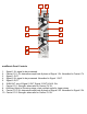
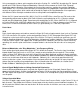
1 2 7 3 8 4 9 10 5 6 modDemix Panel Controls 1. 2. 3. 4. 5. 6. 7. 8. 9. 10. Signal 1 IN: signal to be processed. Carrier/ CV 1 IN: determines amplitude & phase of Signal 1 IN. Normalled to Carrier/ CV. Signal 1 OUT. Signal 2 IN: signal to be processed. Normalled to Signal 1 OUT. Signal 2 OUT. SUM OUT: mix of Signal 1 OUT, Signal 2 OUT & AUX. IN v Carrier/ CV 1 Strength: attenuator for Carrier/ CV IN. AUXiliary INput to Summing stage: chain multiple units for larger mixes.
Getting to Know modDemix: Standard AM, Balanced Modulation, Signal Multiplication, Frequency Mixing, Single Sideband, Double Sideband and even XOR (as in Boolean logic) have all been used to implement “Ring Modulators” for musical purposes in the last 50 years. In a way, Ring Modulation has become a catch-all term for music technology that results in a complex, clangorous, modulated sound.
Using same patch as above, add a negative offset to the Cycling CH. 1 of MATHS, by adjusting CH. 2 panel control to full CCW. Observe Balanced Modulation. Observe the low amount of Carrier Feed-Thorough. Depending upon the Negative Offset added, the Carrier all but vanishes, making the resulting Sidebands more audible. This is the sound most commonly associated with Ring Modulation. Experiment with different amounts of negative offset, which could said to control the Depth of the Ring Modulation.
Mod-Demod To ease the patching of modDemod effects, Signal 2 IN is normalled to Signal 1 OUT, thus connecting the two circuits in series. Carrier/ CV 1 IN is normalled to Carrier CV 2 IN, so that in patching the desired Carrier Signal to Carrier/ CV 2 IN, the modulation and demodulation processes share a single Carrier Signal. Patch Signal to be processed to Signal 1 IN. Patch Carrier to Carrier/ CV 2 IN. Take output from Signal 2 OUT.
Voltage Controlled Crossfading and Panning with ModDemix and MATHS Crossfading Send two signals of your choice to the ModDemix Ch1 and Ch2 INputs. Select a positive-going Control Signal such as a MATHS/Function envelope or a sequence from Rene. Set up a Voltage Mirror with MATHS (Apply Control Signal to be mirrored to CH. 2 Signal IN. Set CH. 2 Attenuvertor to Full CCW. With nothing inserted at CH. 3 Signal IN (so as to generate an offset), set CH. 3 Attenuvertor to full CW. Take output from SUM OUT.