Limited WARRANTY: Make Noise warrants this product to be free of defects in materials Or Construction for a period of two Years from the date of manufacture. Malfunction resulting from wrong power supply voltages, backwards power cable connection, abuse of the product or any other causes determined by Make Noise to be the fault of the user, are not covered by this warranty, and normal service rates will apply.
Ever since completing the QMMG design, I have felt that it needed a good buddy. A patch pal! Say hello to QMMG's best friend, MATHS. MATHS builds on the tradition set into motion in the 1960's by Don Buchla when he adapted the circuits found within analog computers common to engineering labs, for musical purposes. Buchla's "Algebraic Processor, Model 257" changed the way music synthesizers utilized control voltages.
Patch Ideas Voltage Controlled Transient Generator (Attack/ Decay EG) A pulse or gate applied to the Trigger IN of CH. 1 or 4 will start the transient function which rises from 0V to 10V at a rate determined by the Rise parameter and then Falls from 10V to 0V at a rate determined by the Fall parameter. This function is re-trigger-able during the Falling portion.
I/O and Panel Controls Explained Signal IN (CH. 1,2,3,4): Direct Coupled input to associated circuit. Channels 2 and 3 are normalized to a +5V reference for generation of voltage offsets. Trigger IN (CH. 1,4): Gate or Pulse applied to this input will trigger the associated circuit regardless of activity at the Signal IN. The result being a 0V to 10V voltage function, aka Envelope, whose characteristics are defined by the Rise, Fall, Vari-Response and Scale/ Inversion parameters. Activity/ Cycle Switch (CH.
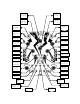
CH. 2 Scaling/ Inversion CH. 3 Scaling/ Inversion CH. 2 Signal IN/ +5V CH. 3 Signal IN/ +5V CH. 1 Trigger IN CH. 4 Trigger IN CH. 1 Signal IN CH. 4 Signal IN Activity/ Cycle Sw. Activity/ Cycle Sw. CH. 4 Rise Panel Control CH. 1 Rise Panel Control CH. 4 Fall Panel Control CH. 1 Fall Panel Control CH. 4 Rise Control IN CH. 1 Rise Control IN CH. 4 Both Control IN CH. 1 Both Control IN CH. 4 Fall Control IN CH. 1 Fall Control IN CH. 4 Scaling/ Inversion CH. 1 Scaling/ Inversion CH.
More Patch Ideas 281 “Quadrature Mode” (West Coast Swirly Bird) In this patch, CH. 1,4 work in tandem to provide functions shifted by ninety degrees. With both Cycle Switches UN-ENGAGED, Patch End of Rise (CH. 1) to Trigger IN CH. 4. Patch End of Cycle (CH. 4) to Trigger IN CH. 1. If both CH.1 and 4 do not begin cycling, engage CH. 1 Cycle Briefly. With both channels cycling, apply their respective Signal OUTputs to two different modulation destinations, for example two channels of the QMMG.
MATHS is FUN FLIP-FLOP (1-Bit Memory) In this patch CH. 1 Trigger IN acts as the “Set” input, and CH. 1 BOTH Contrl IN acts as the “Reset” input. Apply Reset signal to CH. 1 BOTH Control IN. Apply Gate or logic signal to CH. 1 Trigger IN. Set Rise to Full CCW, Fall to Full CW, Vari-Response to Linear. Take “Q” output from EOC. Patch EOC to CH. 4 Signal to achieve “NOT Q” at the EOC OUT. This patch has a memory limit of about 3 minutes, after which it forgets the one thing you told it to remember.