
Instruction Manual


7
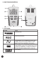
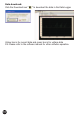
2. Power supply socket
DC voltage supply (6V-9V)
3. USB socket
When transmitting data with PC software, stop recording before
connecting to PC with the USB cable.
4. ON/OFF & data logger status button
Press the button to power on. Hold the button to power off.
Press the button to check which channel data is being recorded. If
display “CHC”, it will record or start recording the current data, and
“CHC-F” means it has recorded the current data and stopped. If display
“CHV” it will record or start recording the voltage data, and “CHV-F”
means it has recorded the voltage data and stopped. If display “CHCV” it
will record or recording the current and voltage data, and “CHCV-F”
means it has recorded the current and voltage data and stopped.
5. Function switch button
Press to switch display to current or voltage data. If the
corresponding sensor is not being connected it will display “-CH-”.
6. Date/Time & START/STOP button
Press the button to cycle on screen view of date and time when
connected. Press the button for 3 seconds for manual recording to
start and “REC” will shown on LCD. If record has started, press the
button 3 second for recording pause and “REC” will stop. Once you stop
recording, it will not record data until next record mode is set up via PC.
7. MAX/MIN button
Press the button to display the maximum or minimum value of the
measurement. If the current reading is for voltage, press this button
for MAX or MIN value of voltage. If the reading is for current, press
this button for MAX. or MIN. value of current. If there is no data, it
will display “0.0”.
8. Voltage Channel
Insert the voltage sensor to this COM to measure and record the
corresponding data.
9. Current Channel
Insert the current sensor to this COM to measure and record the
corresponding data.
10. Battery Cover