INSTRUCTION MANUAL MT250 AC VOLTAGE/CURRENT DATA LOGGER
Contents 1. 2. 3. 4. 5. 6. Page no Introduction.....................................................................................5 Features...........................................................................................5 Function Description..........................................................................6 Data Memory and Data Transmitting....................................................8 Caution Before Connecting.................................................................
Warning! Ÿ Do not attempt to make measurement in flammable gaseous areas! Ÿ When testing non-insulated cable, pay attention to avoiding short circuiting the cable. Ÿ Do not attempt to use the instrument when your hand is wet! Ÿ Do not apply over voltage and currents during measurement. Ÿ Stop using the instrument when there is any structural defect or exposed metal parts. Ÿ Do not install substitute parts or make modifications on the meter. Ÿ Never replace the battery in moist areas.
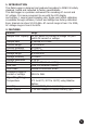
1. INTRODUCTION This Data Logger is designed and produced according to IEC61010 safety standard, tested and inspected to factory specifications. This data logger is a precision instrument for recording AC current and AC voltage. It is more convenient to use with the LCD display and buttons. 1 second rapid sampling rate. Single point offset calibration is available through software, Current and Voltage are factory calibrated. Every channel can store 50,022 data.
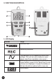
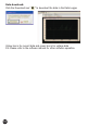
3. FUNCTION DESCRIPTION 1. LCD Display Function Range Date and time Recording indication The waveform of the measuring current and voltage (This unit can only measure a wave whose waveform resembles a sine curve) Battery sign, when displaying completely, it means battery power is full. When there is only a frame icon displayed, it means the battery is flat and should be replaced with a new one.
2. Power supply socket DC voltage supply (6V-9V) 3. USB socket When transmitting data with PC software, stop recording before connecting to PC with the USB cable. 4. ON/OFF & data logger status button Press the button to power on. Hold the button to power off. Press the button to check which channel data is being recorded. If display “CHC”, it will record or start recording the current data, and “CHC-F” means it has recorded the current data and stopped.
4. Data memory and Data transmitting Ÿ If you want to start recording, the corresponding sensor must connect to the data logger or you can not start it. In the process of measurement if the sensor is disconnected because of some reason it will stop recording. Ÿ When the memory is full, the Data Logger will stop recording and turn off, when downloading data to PC you need to turn on the Data Logger. The data can be read time after time until a new setup is done.
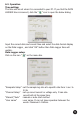
6.2. Operation Time setting: The time will be set when it is connected to your PC. If you find the DATA LOGGER time is incorrect, click the “ ” icon to open the below dialog. Input the correct date and correct time and select the date format display on the Data Logger , and click “OK” button then Data Logger time will update. Data Logger setup: Click on the icon “ ” on the menu bar. “Samprate Setup” : set the sample log rate at a specific rate from 1 sec. to 24 hr.
Data download: Click the Download icon “ ” to download the data in the Data Logger. Yellow line is for current data and green line is for voltage data P.S: Please refer to the software manual for other software operation.
5 11
MAJOR TECH (PTY) LTD South Africa Australia www.major-tech.com www.majortech.com.au sales@major-tech.com info@majortech.com.