Direct Vent Gas Fireplace Models: DVB4136 INSTALLER / CONSUMER SAFETY INFORMATION PLEASE READ THIS MANUAL BEFORE INSTALLING AND USING APPLIANCE WARNING! IF THE INFORMATION IN THIS MANUAL IS NOT FOLLOWED EXACTLY, A FIRE OR EXPLOSION MAY RESULT CAUSING PROPERTY DAMAGE, PERSONAL INJURY OR LOSS OF LIFE. FOR OUR SAFETY Installation and service must be performed by a qualified installer, service agency or the gas supplier. WHAT TO DO IF YOU SMELL GAS: • • • • Do not try to light any appliance.
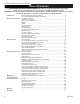
DVB4136 Direct Vent Gas Fireplace Table of Contents PLEASE READ THE INSTALLATION & OPERATING INSTRUCTIONS BEFORE USING APPLIANCE. Thank you and congratulations on your purchase of a CFM Corporation fireplace. IMPORTANT: Read all instructions and warnings carefully before starting installation. Failure to follow these instructions may result in a possible fire hazard and will void the warranty.
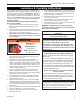
DVB4136 Direct Vent Gas Fireplace Installation & Operating Instructions This gas appliance should be installed by a qualified installer, preferably NFI or WETT (Canada) certified, in accordance with local building codes and with current CSA-B149.1 Installation codes for Gas Burning Appliances and Equipment. If the unit is being installed in a mobile home, the installation should comply with the current CAN/CSA Z 240.4 code. For U.S.A Installations follow local codes and/or the current National Fuel Gas Code.
DVB4136 Direct Vent Gas Fireplace Installation & Operating Instructions Requirements for the Commonwealth of Massachusetts All gas fitting and installation of this heater shall only be done by a licensed gas fitter or licensed plumber.
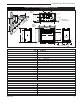
DVB4136 Direct Vent Gas Fireplace Fireplace Dimensions (Installed as Top Vent) Rough Opening Depth V J P I T Q H V Nailing Flange K W K Recessed S - Rough Opening Width Rough Opening Height U F X R D C B Gas Line Access O E A G N L M Electrical Access Fig. 1 Fireplace specifications and framing dimensions. Ref.
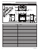
DVB4136 Direct Vent Gas Fireplace Fireplace Dimensions (Installed as Rear Vent) Rough Opening Depth U I S H U J Recessed J V Nailing Flange R - Rough Opening Width Rough Opening Height T F W B Q C D E A Electrical Access G O Gas Line Access M K P N L Fig. 2 Fireplace specifications and framing dimensions. Ref.
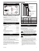
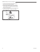
DVB4136 Direct Vent Gas Fireplace V Locating Your Fireplace W X Y Y E A C Y Noncombstible Material Z B Standoff X A D B C D E 3/4” (19 mm) Scribe moulding for use with CFMCabinets B Fireplace F Louvre Assembly top Top of Combustion Chamber LU584-1 Fig. 3 Locating gas fireplace. LU584-1 Locating unit C) **Island F) 2/4/99 Chasedjtinstallation A) Flat on wall B) Cross corner D) *Room divider E) *Flat on wall corner Y) 0” minimum (Check minimum if mantel leg is used) NOTE (Fig.
DVB4136 Direct Vent Gas Fireplace Final Finishing Noncombustible materials such as brick or tile can be extended over the edges of the face of the fireplace. Do not cover the window frame assembly, any vent, louvre assembly top or louvre assembly bottom. If a Trim Kit is to be installed, brick and tile will have to be installed flush with the side of this appliance.
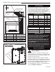
DVB4136 Direct Vent Gas Fireplace Alternate Switch Location 1/2” Gas Supply 1/2” NPT x 3/8” Flare Shutoff Valve The remote switch can be installed on either side of the access door. Mount the switch to the switch bracket provided. Screw the bracket on either side of the frame, line up the screws with the prepunched holes. (Fig. 8) 3/8” Flex Line (from valve) FP297a Fig. 6 Typical gas supply installation.
DVB4136 Direct Vent Gas Fireplace 7. Connect the ground wire of the supply line to the green screw of the socket assembly. 8. Refit the socket assembly back into the electrical box and replace the cover plate. Secure the cable with the clamp on the outside of the unit to prevent strain on the connections. 9. The EB-1 electrical junction box is now ready to supply power to the FK12 or FK24 fan kits if fitted. INSIDE Electrical Box FRONT OF UNIT OUTSIDE T OF N FRO UNIT FP580 Fig. 9 EB-1 receptacle.
DVB4136 Direct Vent Gas Fireplace Optional Top Vent Application The DVB4136 fireplace is shipped as a rear vent unit. If the layout requires a top vent, convert the unit following the steps below. 1. Remove the 10 screws securing outer collar adapter to fireplace. (Fig. 10) 2. Set outer collar adapter aside. 3. Remove insulation from top of unit and discard. Remove the four (4) screws securing flue cover to top of unit and remove flue cover. (Fig. 11) 4.
DVB4136 Direct Vent Gas Fireplace General Venting Your fireplace is approved to be vented either through the side wall, or vertical through the roof. • • • • 12 Only CFM Corporation venting components specifically approved and labelled for this fireplace may be used. Venting terminals shall not be recessed into a wall or siding. Horizontal venting which incorporates the twist lock pipe must be installed on a level plane without an inclining or declining slope.
DVB4136 Direct Vent Gas Fireplace General Venting Information - Termination Location INSIDE CORNER DETAIL G V H A N N D L V E C B V F B ����� ������ B V Ope Operable rable V B B B J X X AIR SUPPLY INLET M I A CFM145a V VENT TERMINATION V V Fixed Closed V K X AREA WHERE TERMINAL IS NOT PERMITTED Canadian Installations1 US Installations2 A = Clearance above grade, veranda, porch, deck, or balcony B = Clearance to window or door that may be opened CFM145a 12” (30cm) DV Te
DVB4136 Direct Vent Gas Fireplace Termination Clearances Termination clearances for buildings with combustible and noncombustible exteriors. Inside Corner Alcove Applications* Outside Corner G= Combustible 6" (152 mm) G F= Combustible 6" (152 mm) Noncombustible 2" (51 mm) V Noncombustible 2" (51 mm) V C V E O F Balcony with perpendicular side wall Balcony with no side wall D C E = Min. 6” (152 mm) for non-vinyl sidewalls Min. 12” (305 mm) for vinyl sidewalls O = 8’ (2.4 m) Min.
DVB4136 Direct Vent Gas Fireplace Twist Lock Pipes 30 When using twist lock pipe it is not necessary to use sealant on the joints. The only areas of the venting system that need to be sealed with high temperature silicone sealant are the sliding joints of any telescopic vent section used in the system.
DVB4136 Direct Vent Gas Fireplace Vent Opening for Combustible Walls 9³⁄₈” (240 mm) 20” (508 mm) Max. Rear Vent Top View 10³⁄₈” (265 mm) DVR584-600 20” DVR584-600 (508 mm) Max. vent no Rear 2/99 djt Framing Detail Fireplace Hearth Fig. 19 Rear vent application, no elbows. 20” (508 mm) Max. Opening for Noncombustible Wall elbows 7¹⁄₂” (190 mm) 45° 45° Fireplace Hearth VO584-100 Fig. 21 Locate vent opening on wall.
DVB4136 Direct Vent Gas Fireplace Finished Wall Rise Vent Termination FP1472 Fig. 25 There must be a 1/2” rise per foot length. Vertical Sidewall Application FP1005 Since it is very important that the venting system maintain its balance between the combustion air intake and the flue gas exhaust, certain limitations FP1472apply and must be strictly as to vent configurations rise in length adhered to.
DVB4136 Direct Vent Gas Fireplace 7’ (2.1 m) 3 x 90° Elbows 3 x 90° Elbows A FP1176 10’ (3 m) B 8’ (2.4 m) Fig. 26 Maximum three (3) 90° elbows per installation. 36" (914mm) Max. 36" (914mm) Max. V584-201 Fig. 29 Maximum vent run with elbows. In Figures 28 & 29, dimension V584-201 A plus B must not be greater than 17’ (5.2m) Horizontal Run 2/99 djt The maximum number of 45° elbows permitted per side wall installation is two (2).
DVB4136 Direct Vent Gas Fireplace Vertical Sidewall Installation Twist Lock Pipe Max. Length 12” (305 mm) Adjustable Zero Clearance Sleeve Step 1 Locate vent opening on the wall. It may be necessary to first position the fireplace and measure to obtain hole location. Depending on whether the wall is combustible or noncombustible, cut opening to size. (Fig. 31) (For combustible walls first frame in opening.
DVB4136 Direct Vent Gas Fireplace X 4” Flex Vent Pipe 12" (305mm) X Spacer Spring 6" (152mm) 5" (127mm) 6³⁄₄" (172mm) FP1182 FP1474 Fig. 35 Install spacer springs. Fig. 34 Horizontal length requirement. Step 4 Step 7 Apply high temperature sealant to 4” (102 mm) and 7” (178 mm) collars or the termination one inch away from crimped end. Guide the vent terminations 4” and 7” collard into their respective vent pipes. Double check that the vent pipes overlap the collars by 2” (51 mm).
DVB4136 Direct Vent Gas Fireplace Do not back fill around snorkel. Below Grade Installation When it is not possible to meet the required vent terminal clearances of 12” (305 mm) above grade level, a snorkel kit is recommended. It allows installation depth down to 7” (178 mm) below grade level. The 7” (178 mm) is measured from the center of the horizontal vent pipe as it penetrates through the wall. Ensure the sidewall venting clearances are observed.
DVB4136 Direct Vent Gas Fireplace Vertical Through-the-Roof Installation Max. Height 40’ (12.2 m) Min. Height 8’ (2.4 m) Max. 10’ (3 m) Support Straps Every 3’ (.9 m) Max. Height 40’ (12.2 m) Min. Height 8’ (2.4 m) Max. 10’ (3 m) FP1183 Fig. 39 Support straps for horizontal runs. Attic Insulation Shield 1 + 2 + 3 + 4 = 270° 1 2 3 4 1. Locate your fireplace. 2. Plumb to center of the (4”) flue collar from ceiling above and mark position. 3. Cut opening equal to 9³⁄₈” x 9³⁄₈” (240 mm x 240 mm). 4.
DVB4136 Direct Vent Gas Fireplace Typical Roof Support Application Typical Ceiling Support Application 3 #5 Sheet Metal Screws per Joint Sealant FP1184 Storm Collar Fig. 42 Venting supports. FP1184 Typical roof/ceiling support apps. Min. 2' (610 mm) TWL101a Fig. 44 Roof flashing. TWL101a Twist Lock Pipe 2/8/99 djt FP1185 Fig. 43 Minimum termination to roof clearance.
DVB4136 Direct Vent Gas Fireplace Venting Components 7TDVRVT - Through the wall Rear Vent Termination 584A venting components rear vent term 4/6/99 djt 584B Vent components Starter Kit 2/25/99 djt 584C Vent components 584D 45 degree elbow Vent Components 2/25/99 90 degree djt elbow 10/20/99djttwistlock 584E 2/25/99 Venting Components 10/20/99 twist lock Telescope vent 584F 2/25/99Components djt Venting 10/20/99 twist lock Pipe sections 2/25/99 djt 10/20/99 twist lock 584G Venting Components Firestop s
DVB4136 Direct Vent Gas Fireplace Operating Instructions Window Frame Assembly Glass Information Only glass approved by CFM Corporation should be used on this fireplace. • • • • The use of any non-approved replacement glass will void all product warranties. Care must be taken to avoid breakage of the glass. Do not operate appliance with glass front removed, cracked or broken.
DVB4136 Direct Vent Gas Fireplace Replacement of Ceramic Hearth Panels (if provided) Screw Screw Burner 1. Remove glass. 2. Set left and right panels on hearth and bring towards front of unit. Grate Hearth Panels Front of Unit H100a Fig. 47 Hearth panel location (if provided). Installation of Logs Remove front glass. (Refer to “Window Frame Assembly Removal” Section, Fig. 46) Remove logs from packaging.
DVB4136 Direct Vent Gas Fireplace 2. Place the left log on the burner by setting the log in the left front corner of the burner up against the brackets. Note the location of the emboss on the log. (Fig. 50) Figure 50 Left Log LG508 Rear Log Figure 51 3. Place rear log. The rear log sits in the firebox at an angle toward the left over the rear log bracket and the left side of the burner. (Fig. 48) Set the log on the rear log pin. (Fig. 48) The right side of the log sits on the rear log bracket.
DVB4136 Direct Vent Gas Fireplace 5. Place the top front log. Set the log by matching the square hole on the bottom Rear Log with the square emboss on the left log. Lay the log at an angle to the left over the fettle. When this log is in place, it must not cover the hole in the left log. (Fig. 53) 6. Place the top center log. Hold the log with the pointed end toward the back. Match the two holes on the bottom of the log with the two pins on the top of the front log.
DVB4136 Direct Vent Gas Fireplace Flame Characteristics Flame & Temperature Adjustment For fireplaces equipped with Hi/Lo valves, flame adjustment is accomplished by rotating the Hi/Lo adjustment knob located near the center of the gas control. (Fig. 54) HI Turn counterclockwise to increase flame height LO Turn clockwise to decrease flame height It is important to periodically perform a visual check of the pilot and the burner flames. Compare them to the illustrations below (Figs. 55, 56).
DVB4136 Direct Vent Gas Fireplace Lighting and Operating Instructions For Fireplaces Equipped with the SIT 820 Valve FOR YOUR SAFETY READ BEFORE LIGHTING WARNING:If you do not follow these instructions exactly, a fire or explosion may result causing property damage, personal injury or loss of life. A. This heater has a pilot which must be lit manually. When lighting the pilot follow these instructions exactly. B. BEFORE LIGHTING smell all around the heater area for gas.
DVB4136 Direct Vent Gas Fireplace Lighting and Operating Instructions For Fireplaces equipped with SIT822 Gas Valve (EN or EP) Warning:If you do not follow these instructions exactly, a fire or explosion may result causing property damage, personal injury and loss of life. FOR YOUR SAFETY READ THE FOLLOWING WARNINGS BEFORE LIGHTING THE APPLIANCE A. This fireplace is equipped with an ignition device which automatically lights the pilot. DO NOT try to light the pilot by hand. B.
DVB4136 Direct Vent Gas Fireplace Lighting & Operating Instructions For Fireplaces equipped with AF4000 Gas Valve Warning: If you do not follow these instructions exactly, a fire or explosion may result, causing property damage, personal injury and loss of life. For Your Safety, Read the Following Warnings before Lighting the Appliance • A. This fireplace is equipped with an ignition device which automatically lights the pilot. DO NOT try to light the pilot by hand. B.
DVB4136 Direct Vent Gas Fireplace Troubleshooting the Gas Control System SIT NOVA 820 Millivolt Valve NOTE: Before trouble shooting the gas control system, be sure external gas shut off is in the “On” position. WARNING: Before doing any gas control service work, remove glass front. SYMPTOM 1. Spark ignitor will not light 2. Pilot will not stay lit after carefully following lighting instructions. 3. Pilot burning, no gas to main burner 4. Frequent pilot outage problem. 20012322 POSSIBLE CAUSES A.
DVB4136 Direct Vent Gas Fireplace Troubleshooting AF4000 Valve If erratic system behavior is observed that cannot be resolved by the methods outlined below, ensure that there is not a transmitter with batteries installed that may be interfering. If a transmitter is packed with batteries installed, its buttons may be depressed sending a constant signal which can interfere with the transmission of desired signals. A transmitter with new batteries can have a range of over 100’ (30.4 m).
DVB4136 Direct Vent Gas Fireplace Troubleshooting AF4000 Valve (continued) Figure 58: AF4000 MOD Module Right Side Continuous PIlot Off/On Switch Remote/Off Switch “S” Pilot Connection Figure 59: AF4000 MOD Module Left Side Learn Button Adjustment FP1762 “I” Pilot Connection AUX Connection ������ ������������������������ ���� FP1763 Pilot will not light/stay lit • Verify the gas supply is turned on.
DVB4136 Direct Vent Gas Fireplace Troubleshooting AF4000 Valve (continued) Flame height adjustment will not work/works backwards • Ensure the black and red leads from the battery pack or the AF4000 110H/L module are securely connected to the red and black leads from the motor drive or H/L latching solenoid located on the valve body (red to red and black to black). • Verify the selector switch on the battery pack is set to DC MOTOR DRIVE or LATCHING SOLENOID, depending upon which device is installed.
DVB4136 Direct Vent Gas Fireplace Instructions for RF Comfort Control Valve The Comfort Control Valve allows remote control of temperature, fan and flame appearance. NOTE: The antenna should hang in free air away from grounded metal. Operation 1. If the manual switch is in remote position, switch it to LOCAL. (Fig. 62) 2. Turn the pilotstat knob counterclockwise from OFF to the PILOT position, push the knob down, and hold in position. The pilot valve opens and allows gas to flow to the pilot burner. 3.
DVB4136 Direct Vent Gas Fireplace Delay Timer Mode Fan Pilot Assembly The shut off delay timer has a maximum of 2 hours and a minimum of zero minutes. To change the timer level, press the time key followed by an arrow key. Pushing the key once will change the timer by 10 minutes. Auto Mode Fan Override During Auto Mode If a lower or higher fan speed is desired when operating in the AUTO mode, the fan speed can be overridden by pushing the fan button followed by the up or down key.
DVB4136 Direct Vent Gas Fireplace LED Count 8 7 Service Action Replace valve Confirm stepper motor connection exists 5 Confirm fan connection exists and works 4 Confirm gas type; jumper in place 3 Replace thermopiles 2 Turn fan ON NOTE: Some keys are not active. Auto Path If the manual switch is set to REMOTE, press the mode button to display AUTO on the transmitter. Does the transmitter display the room and temperature setting? Move switch from LOCAL to REMOTE. Press any key within 30 seconds.
DVB4136 Direct Vent Gas Fireplace Comfort Valve System Control Sequence of Operation with Transmitter Set manual switch to local or remote Five minute wait period Light pilot burner Did the LED stop blinking? Yes Review LED failure analysis Release pilotstat knob Yes Turn pilotstat knob from PILOT to ON Move switch from local to remote. Press any key on transmitter.
DVB4136 Direct Vent Gas Fireplace Conversions must be completed by qualified personnel Fuel Conversion Instructions 2. Insure the rubber gasket (D) is properly positioned CAUTION: Logs may be HOT! Allow to cool before proceeding. and install the new HI/LO pressure regulator assembly to the valve using the new screws (E) supplied with the kit. Tighten the screws securely. (Ref. torque = 25 in/lb) (Fig. 67) 3. Install the enclosed conversion label (F) to the valve body where it can easily be seen. (Fig.
DVB4136 Direct Vent Gas Fireplace 3. Using a 1/2” open end wrench remove the orifices. (Fig. 69) Fuel Conversion Instructions Honeywell Comfort Control Valve ONLY WARNING: The conversion must only be undertaken by a qualified, certified gas appliance installer. Front Burner Orifice (Refer to Table on Page 42) Rear Burner Orifice (Refer to Table on Page 42) Manifold CO130 Fig. 69 Burner orifice replacement. 4.
DVB4136 Direct Vent Gas Fireplace Pilot Orifice Conversion NOTE: It is not necessary to remove the pilot tube for conversion. 1. Loosen pilot hood turning counterclockwise using a 7/16” wrench. (Fig. 74) Pilot Orifice Pilot Hood Index Marks CO106 Fig. 75 Remove pilot orifice. Pilot Bracket CO105 Fig. 74 Remove pilot hood. 2. Remove pilot orifice with needlenose pliers. (Fig. 75) 3. Install conversion pilotCO105 orifice. Gas Conversion 4. Reinstall pilot hood.
DVB4136 Direct Vent Gas Fireplace Maintenance Burner and Burner Compartment It is important to keep the burner and the burner compartment clean. At least once per year the logs and lava rock/ember material should be removed and the burner compartment vacuumed and wiped out. Remove and replace the logs as per the instructions in this manual. Always handle the logs with care as they are fragile and may also be hot if the fireplace has been in use.
DVB4136 Direct Vent Gas Fireplace 2 1 1c 1f 7 1g 1d 3 1e 17a,b 1b 1h 1a 6 4 1h 5 11 18a,b 9 LOCAL 8 12 10 21 14 20 23a 33 26 OT PILOFF • 19 LE D REMOTE •ON 16 13 28 27 15 34 29 22 23b 31 46 30 32 37a,b 38 35 39 24a,b 40 44 41 23c 25a,b 43 42 36a-d 54 45 48 50 56 52 53 58 55 51 57 47 49 CFM Corporation reserves the right to make changes in design, materials, specifications, prices and discontinue colors and products at any time, 12322 without n
DVB4136 Direct Vent Gas Fireplace DVB4136 (continued) Ref. 1e. 1f. 1g. 1h. 2. 3. 4. 5. 6. 7. 8. 9. 10. 11. 12. 13. 14. 15. 16. 17a. 17b. 18a. 18b. 19. 20. 21. 22. 23a. 23b. 23c. 24a. 24b. 25a. 25b. 26. 27. 28. 29. 30. 31. 32. 33. 34. 35. 36a.
DVB4136 Direct Vent Gas Fireplace DVB4136 (continued) Ref. 36b. 36c. 36c. 36d. 36e. 37a. 37b. 38. 39. 40. 41. 42. 43. 44. 45. 46. 47. 48. 49. 50. 51. 52. 53. 54. 55. 56. 57. 58. 59. 60. 61. 62. 63. 64. 65. 66. Description Orifice - Front Burner (#57 / .043”) - Nat. Orifice - Rear Burner (#54 / .0585”) - LP Orifice - Rear Burner (#53 / .0595”) - LP Orifice - Rear Burner (#41 / .096”) - Nat. Orifice - Rear Burner (39 / .0995) - Nat. Regulator Head - Nat.
DVB4136 Direct Vent Gas Fireplace Optional Accessories Fan Kits FK12 Fan Assembly 1. Open louvre assembly bottom. 2. Install FK12 fan in back of unit between hearth supports. (Fig. 77) 3. Secure fan on velcro strips. 4. Power to the fan can be supplied by plugging the supply lead into a conveniently located wall socket or by using a hard-wired EB-1 connector box. 5. Be sure fan motor does not touch hearth supports.
DVB4136 Direct Vent Gas Fireplace Remote Controls Optional remote control units are available to control different functions of the appliance. Model RC1 RC2 IMTFK Functions Controlled ON/OFF ON/OFF and Temperature Wall mounted thermostat control Rear Ceramic Panel Back of Firebox Burner Ceramic Refractory Panels Rear Log Support Ceramic refractory panels are available to line the firebox area.
DVB4136 Direct Vent Gas Fireplace Arch/Square Face Kit for the DV4136 Romanesque - Arch 41DVARFKB 41DVARFKR 41DVARFKS Romanesque - Square 41DVSRFKB 41DVSRFKR 41DVSRFKS Marquette - Arch 41DVAMTKB 41DVAMTKR 41DVAMTKS Marquette - Square 41DVSMTKB 41DVSMTKR 41DVSMTKS 50 Black Rustic Bronze Pewter Black Rustic Bronze Pewter Black Rustic Bronze Pewter Black Rustic Bronze Pewter Battery Backup The use of the battery backup, Model DVTBBK, will allow your fireplace to continue operating in the event electric power
LIMITED LIFETIME WARRANTY DVB4136 Direct Vent Gas Fireplace PRODUCT COVERED BY THIS WARRANTY All Vermont Castings gas stoves, gas inserts, and gas fireplaces, and all Majestic brand gas fireplaces equipped with an Insta-Flame Ceramic Burner, or standard steel tube burner.
Efficiency Ratings Model DVB4136RN DVB4136RP DVB4136IN DVB4136IP DVB4136RFN DVB4136RFP EnerGuide Ratings Fireplace Efficiency (%) 62.4 62.4 62.4 62.4 62.4 62.4 Steady State (%) Fan-OFF Fan-ON 82 83 83 84 82 83 83 84 82 83 83 84 CFM Corporation 2695 Meadowvale Blvd. • Mississauga, Ontario, Canada L5N 8A3 800-668-5323 • www.cfmcorp.com D.O.E.