
Technical data


32
11.0 Commissioning
© Baxi Heating UK Ltd 2014
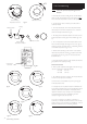
Pump
Automatic Air
Vent
Pressure Gauge
Screw
bar
0
1
2
3
4
Fig. 59
Selector Switch
Central Heating
Temperature Control
Calibration
Control
Reset
bar
0
1
2
3
4
Pump
Fig. 61
Fig. 60
Display
Heat Exchanger
Automatic Air Vent
Fig. 58
11.1 Commissioning the Boiler
1. Reference should be made to BS:EN 12828 & 14336 when
commissioning the boiler.
2. At the time of commissioning, complete all relevant sections of
the Benchmark Checklist at the rear of this publications.
3. Open the mains water supply to the boiler.
IMPORTANT: The heat exchanger air vent on top of the
boiler (Fig. 58) MUST be opened before filling the primary
system.
4. Open all hot water taps to purge the DHW system.
5. Ensure that the filling loop is connected and open, then open
the heating flow and return valves on the boiler.
6. Open the screw on the automatic air vent on the pump body
(Fig. 59).
7. The system must be flushed in accordance with BS 7593 (see
Section 6.2) and the flushing agent manufacturers instructions.
8. Pressurise the system to 1.5 bar (Fig. 60) then close and
disconnect the filling loop.
9. Turn the gas supply on and purge according to in GB BS 6891
and in IE I.S. 813 “Domestic Gas Installations”.
10. Test for gas tightness.
11. Hinge the facia panel upwards and refit the case front panel.
Tighten the securing screws.
12. Having checked:
• That the boiler has been installed in accordance with these
instructions.
• The integrity of the flue system and the flue seals.
• The integrity of the boiler combustion circuit and the
relevant seals.
Proceed to put the boiler into operation as follows:
13. The Combustion Check procedure as shown by the chart in
11.2 is mandatory. The method of setting the boiler to operate
at maximum and minimum rates to comply with the procedure
is described below.
14. Ensure that all external controls are calling for heat. The actual
current boiler temperature is shown on the display.
15. Turn both control knobs fully anticlockwise, then quickly turn
the right hand knob 1/4 clockwise twice and back fully
anticlockwise.
16. The display will now alternate between ‘SF’ and the current
boiler temperature and both green LEDs will flash.
17. To set to maximum rate.
Turn the left hand knob fully clockwise. As the knob is turned the
display will change, indicating the fan speed.
18. The display will show ‘00’, indicating maximum rate, then
revert to ‘P ‘ alternating with the current boiler temperature.
19. To set to minimum rate.
Turn the left hand knob fully anti-clockwise. As the knob is turned
the display will change, indicating the fan speed. When the display
reads ‘ 0’ the boiler runs at minimum rate.
20. This function is maintained for 20 minutes unless the
maximum CH temperature is exceeded. The function can be
disabled at any time by turning the right hand knob.