
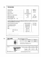
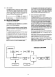
Technical data

3.3
3.4
3.5
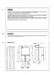
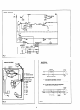
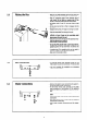
Fitting the flue
-
Measure the wall thickness and cut flue duct and
air inlet duct to required length, (see Section 1.4).
- Peel off protective paper from adhesive side of
cork gasket (A) and place on mating side of flue
turret(B) lining up screw holes and press down.
- Fit locking ring (C) and ‘0’ ring over the air inlet
duct.
- Fit flue duct and turret so that it engages into the
terminal.
D - Engage locking ring over lugs by turning in an anti-
clockwise direction viewed from behind turret.
-
Pass the assembled flue through the wall.
- If long flue sections are used (up to 3 metres) and
difficulty is found, these can be assembled whilst
being passed through the wall.
- Seat the turret onto the top of the appliance ensu-
ring the gaskets are in position.
- Secure with 4 screws provided.
- Do not fit plastic turret cover or the front case un-
til electrical connections have been made and the
appliance tested for gas and water soundness (see
Section 5.1).
- A sealing ring (D) is supplied which can be used to
seal the air inlet duct to wall joint-externally.
-
Make good inside wall surface.
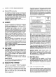
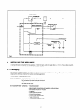
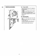
Gas Connection
Fit the gas service cock provided using the fine
c$
filter/washer to seal the connection. Fit the nut and
olive onto the 15 mm gas supply pipe and tighten.
’ andpurgeKP:331.3).
Test the complete gas installation for soundness
I
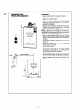
Water connections
-
Remove the plastic covers protecting the water in-
let and the water outlet connections.
-
Fit the water service cock provided to the right
hand connection at the bottom of the appliance
using the coarse filter/washer to seal the connec-
tion.
-
Fit the nuts and olives onto the supply and delivery
pipes.
-
Connect the inlet supply to the water service cock
and tighten.
-
The water service cock supplied with the appliance
incorporates a drain plug.
- Ensure that all water connections are fully tighte-
ned.
9