
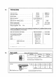
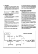
Technical data

-.
3.2
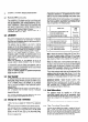
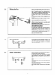
Preparing and
Preparation :
fitting the appliance
y---
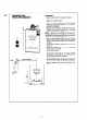
- Remove the bottom trim by pulling forwards.
- Slide the controls facia plate (PI upwards to disen-
gage from retaining bracket.
- Release the front case by removing the four fixing
screws and washers positioned at the top, bottom
and centre of appliance.
1
142
1: 142 j
-
--c
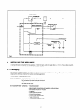
197.5 mm minimum
I
7
.
---
!-
r I
I
I
i
- Remove the front case by lifting off the top loca-
ting lugs and pulling forward to clear the water
section at the base of the appliance.
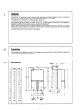
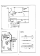
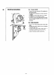
NOTE
: A template is not supplied with this appliance.
Particular care is therefore necessary to ensure that
the appliance mounting bracket is fitted level and po-
sitioned accurately, relative to the flue.
- Refer to the drawings opposite for rear and side
flue applications and/or to the dimensions given in
Section 1.4, refer also to Section 2.4 for flue termi-
nal siting.
- Set out and rill hole for flue using a 100 mm (4 in)
core drill.
- Using the dimension 290 mm (11.4 in) accurately
mark position for bracket.
- Drill and plug the wall.
-
Fix bracket to wail using No. 12 screws provided,
ensuring that the bracket is level. If necessary ad-
just bracket, finally secure in position.
-
Hang the appliance on the bracket, and re-check
for level. Mark bottom fixing holes, remove ap-
pliance, drill and plug the wall to suit No. 12 screws.
- Re-hang appliance and secure with screws provi-
ded.