
Technical data
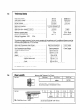

2.7
Air supply
The appliance does not require any purpose provided
ventilation unless installed in a compartment. A compart-
ment enclosing an appliance requires high and low level
openings. These openings must either communicate with
a room or internal space or be direct to outside air. The
minimum FREE area of the opening must be :
High
level
Low level
Air from mom or internal space 258 cm2 (40 in2) 258 cm* (40 irL2)
Air direct from outside
129 cm2 (20 in.2) 129 ails (20 in*)
2.8
Electrical Connections
The appliances must be earthed.
The installation should be undertaken by a competent
electrician and should be in accordance with the current
edition of the IEE Wiring Regulations.
Particular attention should be paid to cross bonding.
The appliance must be provided with a means of isolation.
If installed in a bathroom the means of isolation must be
external to the bathroom or a double pole cord switch fit-
ted.
Acceptable methods of connection are :
1. A switched, double pole fused spur with 3 mm contact
separation on all poles.
2. A double pole switch where the supply must be suita-
bly fused 3 A.
3. An un-switched socket outlet compling with BS 1363.
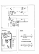
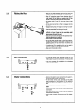
The method of connecting the plug brown wire to live (U
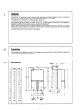
blue wire to neutral (N) and green/yellow to earth ( ),
see fig. 3.
A three core cable should be used and a heat resisting ca-
ble of 0.75 mm2 (24 x 0.2 mm) is considered suitable.
2.9
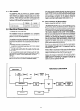
Description of Operation
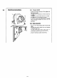
The cable should be passed through the gland on the top
of the appliance and the clamp tightened to secure the
cable. Ensure current carrying conductors become taught
before earthing conductor should cable slip from the
cord anchorage. Connection to the appliance should be
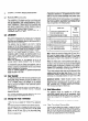
made in accordance with diagram (see section 3,6,2).
Read in conjunction with figs 1. 2 and 4).
The controls on the BRITONY II FF are comprised of a ran-
ge of thermal, electric and electronic switches. Broadly, the
thermal controls are for the pilot flame supervision, the
electrical controls are functional switching and the electro-
nic controls act as a security for the functional controls.
The circuit is designed so that, under normal conditions,
the fan runs continuously at low speed and automatically
changes to high speed when the gas valve opens. If,
however, the incoming air temperature approaches 0 “C
the integral frost protection thermostat interrupts the
low fan speed signal. Under this condition, if there is a de-
mand for hot water, then the fan recommences at.high
speed. There is an in-built delay circuit to prevent the
safety devices operating prematurely.
The pilot can only be established under the control of the
thermocouple flame failure circuit after the mains electri-
city connection is made since it is dependent upon the
energising of relay-RLI.
If the air flow is not proved on high speed the flame failure
device will operate by interrupting the thermocouple as a
result of the failure of the circuit through relay-RLI.
Additional security is provided for the condition where,
because the linkage is mechanical, the main gas burner is
initiated but the microswitch has remained in the low fan
speed position. If the burner is sensed in the low fan
speed circuit the appliance fails safe.
ELECTRIC SUPPLY
FUNCTIONAL FLOW DIAGRAM
.
THERMOSTAT ’
L
r
FAN
1r
17
AA
I
L
r
I
THERM0
THERM0
MICRO SWITCH
RELAY
- RL2
i RELAY L
7
RLl
r ’
COUPLE -t ELECTR’C
VALVE
SAS VALVE
I