
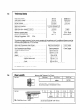
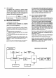
Technical data

2.
INSTALLATION REQUIREMENTS
2.1
Related Documents
The installation of the heater must be in accordance with
the relevant requirements of the Gas Safety (Installation
and Use) Regulations 1984, Building Regulations, the cur-
rent IEE Wiring Regulations and the Byelaws of the local
water undertaking. It should also be in accordance with
any relevant requirements in British Standard Codes of
Practice. Detailed recommendations are contained in the
following British Standard Codes of Practice :
CP 331 : Pt. 3 : 1974.. BS 5546 : 1979, BS 5440 : Pt. 1 :
1978 and BS 5440 : Pt. 2 : 1976.
2.2
Location
The location chosen for the appliance must permit the
provision of a satisfactory flue termination. The location
must also permit adequate space for servicing and air cir-
culation around the appliance.
The appliance may be installed in any room or internal
space although particular attention is drawn to the requi-
rements of the IEE Wiring Regulations and, in Scotland,
the electrical provisions of the Building Standards applica-
ble in Scotland, with respect to the installation of a heater
in a room or internal space containing a bath or shower.
Where a room sealed appliance is installed in a room
containing a bath or shower, any electrical switch or ap-
pliance control, utilising mains electricity should be so si-
tuated that it cannot be touched by a person using the
bath or shower.
Where the installation of the appliance will be in an
unusual location special procedures may be necessary
and BS 5546 gives detailed guidance on this aspect.
A compartment used to enclose the appliance must be
designed and constructed specifically for this purpose. An
existing cupboard or compartment may be used provided
that it is modified for the purpose.
Details of essential features of cupboard/compartment
design are given in BS 5546.
2.3
Gas Supply
An adequate sized gas meter must be connected to the
service pipe. Where necessary the local Gas Region of Bri-
tish Gas will arrange for the existing meter to be checked
or for a suitable meter to be installed. On no account
must any work be carried out on the gas meter other
than by the local Gas Region or their specifically authori-
sed contractor.
Installation pipes should be fitted in accordance with CP
331 : 3. Pipework from the meter must be of adequate
size. Pipes of a smaller size than the gas connection
should not be used.
The complete installation must be tested for gas sound-
ness and purged in accordance with CP 331 : 3.
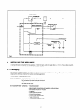
2.4
Siting the Flue Terminal
The flue must be installed in accordance with BS 5440 : Pt.
1.1978. The flue is suitable for STRAIGHT flue application
only.
The following notes are intented to give general guidance.
The standard flue set is suitable for walls having a thick-
ness of 75 mm (3 in.) to 612.5 mm (24 in.) for rear outlet
fluing or up to 500 mm (19,5 in.) for side outlet fluing.
Other flue options are available to a maximum of 3 m (9
ft. 8 in.) to special order.
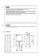
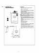
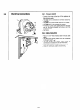
2.5
Wall Mounting
The appliance should be installed on a flat non-
combustible material which will not reverberate. What
ever the thickness of the wall a hole 100 mm (4 in.) in dia-
meter will be required for the app!iance flue assembly. It
is recommended that a core drill be used to form this
hole.
For dimensions and clearances see sections 1.2 and 1.3.
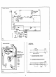
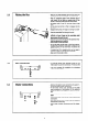
2.6
Flue Terminal Assembly
The appliance must be installed so that the flue terminal
is exposed to external air. The appliance must NOT be ins-
talled so that the terminal discharges into another room
or space such as an outhouse or lean-to. It is important
that the position of the terminal allows a free passage of
air across it all times. The minimum acceptable spacings
from the terminal to obstructions and ventilation ope-
nings are specified in the following chart.
1.
I I
Diily below an openable window, air vent
or any other ventilation opening.
I
300 mm (12 in.)
I
I
I
2. 1 Below qutterinq, drain pipes or soil pipes. 1 75mm(3iIL)
13. I
Below balconies or eaves. 1 2OOmm(8 ill.) 1
4. Above adjacent ground or balcony level 3OOmm(12in.)
5. From vertical drain pipes or soil pipes. 7.5 mm (3 in.)
16.
1
From intemal or external comers. 1 3OOmm(12in) 1
7.
From a surface facing the terminal
8.
From a terminal facing the terminal
600 mm (24 in)
1200 mm (46 h.)
Note -Where the terminal is fitted within 850 mm (34 in.)
of a plastic or painted gutter or 450 mm (18 in.) of pain-
ted eaves an aluminium shield of at least 750 mm (30 in.)
long should be fitted to the underside of the gutter or
painted surface.
Where the lowest part of the terminal is less than 2 m.
(6.5 ft) above the level of any ground, balcony, flat roof
or place to which any person has access and which adjoins
the wall in which the terminal is situated must be protec-
ted by a guard of durable material (a terminal guard is
available from Chaffoteaux Limited) or from Quinnell Bar-
rett & Quinnell. 01.639.1357. (GC No 381.782)
The air inlet/products outlet duct and the terminal of the
appliance must not be closer than 25 mm (I in.) to any
combustible material. Detailed recommendations on the
protection of combustible material are given in BS 5440
Pt. 1 : 1978 (Sub-clause 20.1).
IMPORTANT NOTICE: TIMBER FRAMED HOUSES. If the
appliance is to be fitted in a timber framed building it
should be fitted in accordance with the British Gas publi-
cation “Guide for Gas Installations in Timber Framed Hou-
sing” reference DM2. If in doubt advice must be sought
from the local Gas Region of British Gas.
The flue may be fitted from inside or outside of the buil-
ding. If fitting from inside the flue duct should be assem-
bled into the air inlet duct and the assembly passed trough
the hole in the wall. The outside diameter of the terminal is
the same as outside diameter of the air inlet duct.
4