
Technical data
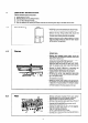


7.12
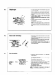
Replacement of Microswitch
- Isolate electrical
SUPPIY.
- Part connector plug on leads to microswitch.
-
Remove two lock nuts (4 mm) from microswitch re-
taining screws.
- Remove screws securing microswitch.
- Remove switch together with plastic insulating plate.
-
Renew microswitch and replace in reverse order.
7.13
7.14
7.15
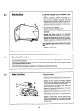
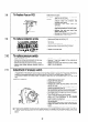
Adjustment of Microswitch operating mechanism
- Re-establish electrical supply - leave gas cock and hot water taps off.
- Set temperature selector to f.
- Slacken lock screw (B) using I,5 mm hexagon socket screw kev.
- Check whether fan is at high or low speed.
- If fan at low speed screw out adjustment screw (A) until high speed is obtained, then screw in until high Speed
k observed then a further 3 full turns.
-
If fan runs at high speed screw in adjustment screw (A) until low speed is observed then a further 3 full turns.
- With the fan now at low speed turn on a hot tap.
-
Screw adjustment screw (A) out until high speed fan operation is obtained.
- Continue unscrewing adjustment screw (A) for a further 1 turn.
- Hold screw in position with screwdriver and lock with hexagon socket screw (8).
- Check operation of microswitch (see Section 5.4).
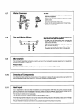
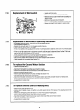
To replace the Gas and Water Section
- Remove the burner see 6.2.
- Disconnect microswitch bv parting plug connector on leads.
- Remove the conductor lead at thermoelectric valve (see Section 7.31.
- Remove thermocouple lead at PCB.
- Remove spark electrode lead from piezo cartridge (see Section 7.6).
- Disconnect the gas union at rear of gas section.
-
Disconnect the water connections from the water section. Mains inlet and water section to heating bodv.
- Remove the two screws securing the burner base to the rear chassis.
- Re-assemble in reverse order.
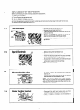
To replace Ceramic Liners in Heating Body
-
Remove the burner (see Section 6.2).
- Remove two threaded screws (A) (Section 6.4), which secure the top front panel of the heating body to the
flue hood.
- Remove six self tapping screws (B) (Section 6.4). from front panel of heating body.
- Slide out front and side ceramic liners from locating channels.
-
Ease heat exchanger forward to allow rear ceramic liner to be lifted clear of lower channel.
- Lift panel and withdraw lower edge first.
- Re-assemble in reverse order.
21