
Technical data
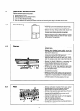

7.8
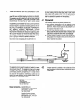
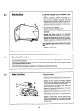
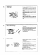
To Replace Fuse or PCB
Isolate electrical supply.
l
A
(A) FUSE : - Pull out fuse holder (A) from board and
slide fuse out of holder.
(B) PCB
: - Remove connections (fan. microswltch.
pressure switch and ionisation lead
complete with sleeve)
- Disconnect mains sup~lv cable from
termtnals.
- Remove two nuts and washers (6) retai-
ning thermocouple and conductor lead.
-
Remove fuse and ease board from
plastic retaining clips.
- Remove four screws and remove PCB.
- Re-assemble in reverse order.
7.9
7.10
7.11
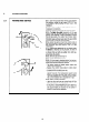
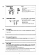
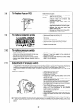
To replace ionisation probe
- Remove pilot tube (see Section 6.3).
-
\ . .
- Remove combustion chamber front cover (see Sec-
tion 6.4 a).
- Disconnect ionisation lead.
- Remove screw (A) secunng probe to bracket.
- Pull out probe whilst feeding lead through burner.
- Replace in reverse order.
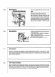
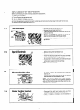
To replace pressure switch
-
Isolate electrical supply.
- Remove two screws securing plastic turret cover.
-
Pull off tag connectors from terminals.
- Remove low pressure tube from pressure switch.
- Remove two
screws
securing pressure switch to
bracket.
- Lift off pressure switch.
- Remove ‘0’ ring from spiggot on the underside of
the pressure switch.
- Replace in reverse order referring to colour coding
label on top of appliance.
Adjustment of pressure switch
a) If Pilot eXtinctiOn occur within 5/10 seconds of turning hot tap off, it is possible that the pressure switch is out
of adjustment. If the pressure switch remains in the high flow position in excess of S/IO seconds after the fan
switching to low speed interruption of the thermoelectrical current to the flame failure valve occurs,
It is possible to adjust the pressure switch to ensure a rapid return of the pressure switch from high to low
flow.
Adjustment Sequence :
- Adjusting the pressure switch
- Ensure the front case is on.
- Isolate electrical supply.
- Remove two screws securing plastic turret cover
and lift off cover.
- Remove terminal cover from pressure switch ex-
posing the adjusting screw (A).
- Set a multimeter to 240 V scale and connect it across
the common and one other terminal of the switch.
- Re-establish electrical supply and ensure that gas is
off at gas control.
- ‘Turn on a hot tap to give high fan speed.
- Using a suitable screwdriver screw the adjusting
screw (A) in until changeover of the pressure
switch contacts are observed.
- Screw out adjusting screw (A) 3 turns to achieve
the setting point.
- Check operation of the pressure switch (see section 5.5).
- Replace the plastic terminal cover on the pressure
switch.
- Replace the plastic turret cover and fixing screws.
b) If main burner extinction occurs during hot water demand, it is possible that the pressure switch is out of ad-
justment. Screw adjusting screw (A) out until flush with top of moulding, then follow adjustment sequence
above.
20